2 software mode, 8 wiring the twisted pair rj-45 connectors, Wiring the twisted pair rj-45 connectors – Kramer Electronics TP-185 User Manual
Page 16: Figure 9: cat 5 pinout, Table 5: utp connector pinout
Wiring the Twisted Pair RJ-45 Connectors
13
13
7.1.5.2 Software Mode
In Software mode, the TP-185 routes the data and reply based on the Protocol 2000
commands received from the PC or other device connected to any of the inputs.
The following example illustrates a typical command sequence. The destination and
return paths to and from the end-user device are set (TP-185 control commands),
then an end-user device command is sent to the defined destination. The TP-185
differentiates between the two types of commands and acts accordingly.
The sequence is as follows:
1. Set destination path for command
2. Set return path
3. Send end-user command sequence
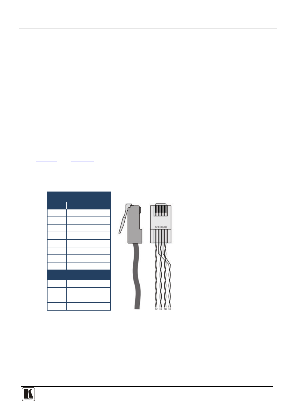
8 Wiring the Twisted Pair RJ-45 Connectors
define the TP pinout using a straight pin-to-pin cable with
RJ-45 connectors. When using STP cable, connect/solder the cable shield to the RJ-45
connector shield.
Table 5: UTP Connector Pinout
EIA /TIA 568B
Figure 9: CAT 5 Pinout
PIN
Wire Color
1
Orange / White
2
Orange
3
Green / White
4
Blue
5
Blue / White
6
Green
7
Brown / White
8
Brown
Pair 1
4 and 5
Pair 2
1 and 2
Pair 3
3 and 6
Pair 4
7 and 8