3 setting the reply source or machine number, Setting the reply source or machine number, N 7.1.3 – Kramer Electronics TP-185 User Manual
Page 14
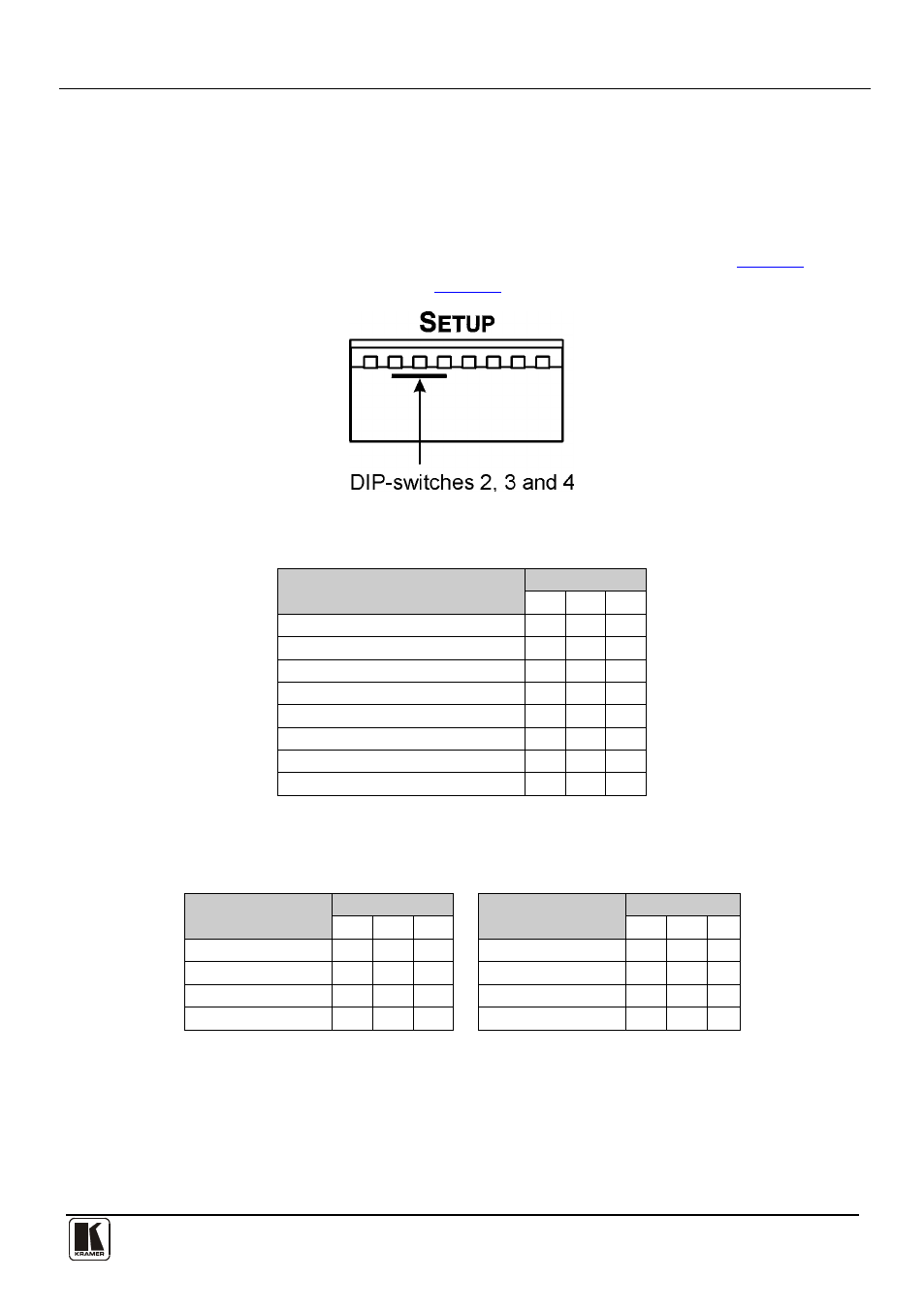
Setting the DIP-switches on the TP-185
11
11
When DIP-switch 1 is:
• Up, Reply is disabled (default)
• Down (ON), Reply is enabled
7.1.3
Setting the Reply Source or Machine Number
DIP-switches 2, 3 and 4 set either the reply source (in Hardware mode
) or
machine number (in Software mode
).
Figure 6: TP-185 Reply Source or Machine Number DIP-switches
Table 2: Hardware Mode Reply Source DIP-switch Setting
Reply Source
DIP-switch
2
3
4
Reply is taken from output 1 (default) OFF OFF OFF
Reply is taken from output 2
ON OFF OFF
Reply is taken from output 3
OFF ON OFF
Reply is taken from output 4
ON ON OFF
Reply is taken from output 5
OFF OFF ON
Reply is taken from output 6
ON OFF ON
Reply is taken from output 7
OFF ON ON
Reply is taken from output 8
ON ON ON
Note: When there is more than one TP-185 attached to the RS-485 bus only one unit
can have a reply path set.
Table 3: Software Mode RS-485 Machine Number DIP-switch Setting
Machine Number
DIP-switch
Machine Number
DIP-switch
2
3
4
2
3
4
1
OFF OFF OFF
5
OFF OFF ON
2
ON OFF OFF
6
ON OFF ON
3
OFF ON OFF
7
OFF ON ON
4
ON ON OFF
8
ON ON ON
When there is more than one TP-185 attached to the RS-485 bus each unit must have
a unique machine number.