On 4.2 – Kramer Electronics TP-134 User Manual
Page 8
TP-133/TP-134 - Defining the TP-133/TP-134 Line Transmitter and Receiver
5
5
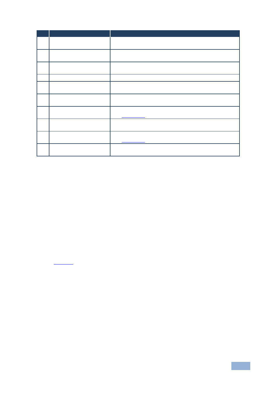
#
Feature
Function
1
PC IN 15-pin HD
Connector (M)
Connect to a computer graphics video source
2
AUDIO IN 3.5mm Mini
Jack
Connect to an unbalanced, stereo audio source
3
RS-232 9-pin D-sub
Connector (F)
Connect to the RS-232 device (PC or controller)
4
POWER LED
Lights red when the unit receives power
5
5.3V DC Power
Connector
Connect to one of the supplied +5.3V DC power adapters.
Center pin positive
6
BAL. AUDIO IN 5-pin
Terminal Block
Connect to a balanced, stereo audio source
7
BAL. AUDIO OUT 5-pin
Terminal Block
Connect to a balanced, stereo audio acceptor (loop output),
see
Section 5.1
8
AUDIO OUT 3.5mm Mini
Jack
Connect to an unbalanced, stereo audio acceptor (loop
output)
9
LINE OUT RJ-45
Connector
Connect to the LINE IN RJ-45 connector on the
TP-134,
see
Section 5.2
10
PC VIDEO OUT 15-pin
HD Connector (F)
Connect to a computer graphics monitor (loop output)
4.2
Defining the TP-134 Automatic PC/Audio/Data Line
Receiver
The
TP-134 is a high-performance receiver that accepts the computer
graphics/audio/RS-232 data from the Kramer
TP-133 via TP cabling at its RJ-45
LINE IN input. The
TP-134 outputs a computer graphics signal, an unbalanced
stereo audio signal, a balanced stereo audio signal and RS 232 data signal.
In addition, the
TP-134 features color skew and equalization control for the video
signal.
defines the
TP-134.