2 wiring the tp rj-45 connectors, Wiring the tp rj-45 connectors, Figure 4: connecting to a balanced acceptor – Kramer Electronics TP-134 User Manual
Page 12: Figure 5: connecting to an unbalanced acceptor, Figure 6: cat 5 pinout, N 5.1, N 5.2, On 5.1
TP-133/TP-134 - Connecting the TP-133/TP-134
9
9
5.1
Connecting the Audio Output to Balanced and
Unbalanced Audio Equipment
illustrates how to connect the
TP-133/TP-134 balanced audio output to a
balanced acceptor.
Figure 4: Connecting to a Balanced Acceptor
illustrates how to connect the
TP-133/TP-134 balanced audio output to
an unbalanced acceptor.
Figure 5: Connecting to an Unbalanced Acceptor
5.2
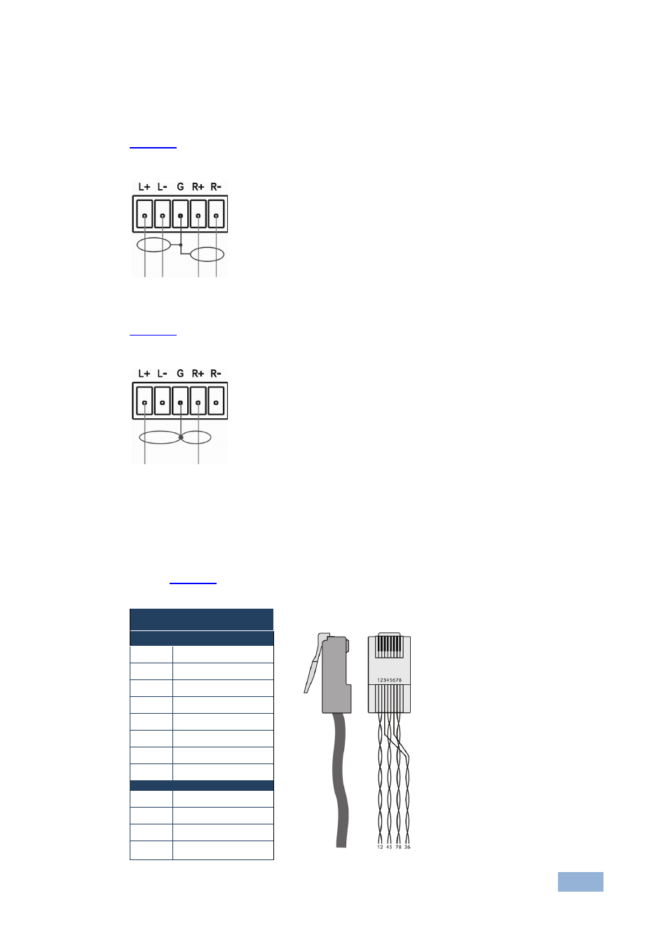
Wiring the TP RJ-45 Connectors
When using STP cable, connect/solder the cable shield to the RJ-45 connector
shield.
defines the TP pinout using a straight pin-to-pin
cable with RJ-45
connectors.
EIA /TIA 568B
Figure 6: CAT 5 Pinout
PIN
Wire Color
1
Orange / White
2
Orange
3
Green / White
4
Blue
5
Blue / White
6
Green
7
Brown / White
8
Brown
Pair 1 4 and 5
Pair 2 1 and 2
Pair 3 3 and 6
Pair 4 7 and 8