3 your pt-120 xga line receiver, Your pt-120 xga line receiver, Figure 3: pt-120 xga line receiver – Kramer Electronics PT-110 User Manual
Page 9: Table 2: wp-110 xga line transmitter features, Section, Table 2, Defi, Your xga line transmitter(s) / receiver
Your XGA Line Transmitter(s) / Receiver
7
Table 2: WP-110 XGA Line Transmitter Features
#
Feature
Function
1
XGA IN 15-pin HD (F)
Connector
Connect to the XGA source
2
ON LED
Illuminates when receiving power
3
HS
Switch
Slide the switch to the left
to change the HS polarity to (NEG.) negative
polarity
; slide the switch to the right (NORM.) to retain the polarity
4
VS
Switch
Slide the switch to the left
to change the VS polarity to (NEG.) negative
polarity
; slide the switch to the right (NORM.) to retain the polarity
5
LINE OUT RJ-45
Connector
Connects to the LINE IN RJ-45 connector on the PT-120 or TP-120
XGA Line Receiver
6
POWER
SUPPLY
GND PIN
Connect (-) to the Ground
+12V DC PIN
Connect (+) to the connector for powering the unit
4.3
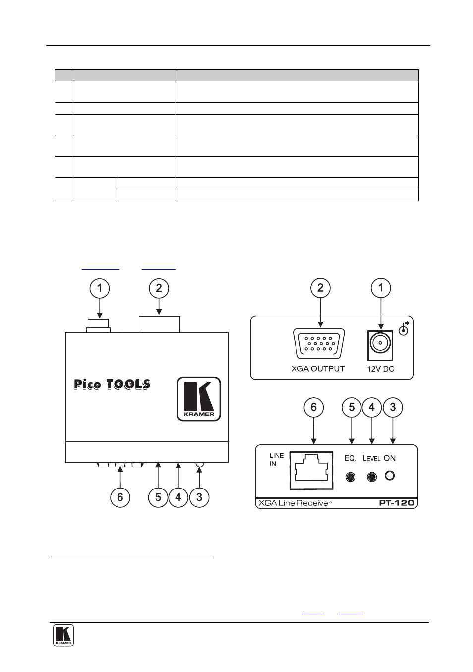
Your PT-120 XGA Line Receiver
This section describes the PT-120 XGA Line Receiver.
and
define the topside of the PT-120 XGA Line Receiver:
Figure 3: PT-120 XGA Line Receiver
1 By default, both switches are set to the right
2 Downgoing syncs
3 SYNC
4 Using a UTP cable with CAT 5 connectors at both ends (the PINOUT is defined in
Table 5
and
Figure 6
)