Defining the wall plates (for the united states) – Kramer Electronics SV-305 User Manual
Page 6
KRAMER: SIMPLE CREATIVE TECHNOLOGY
Defining the Wall Plates (for the United States)
4
4.2 SV-303, SV-304, and SV-305 (for the United States)
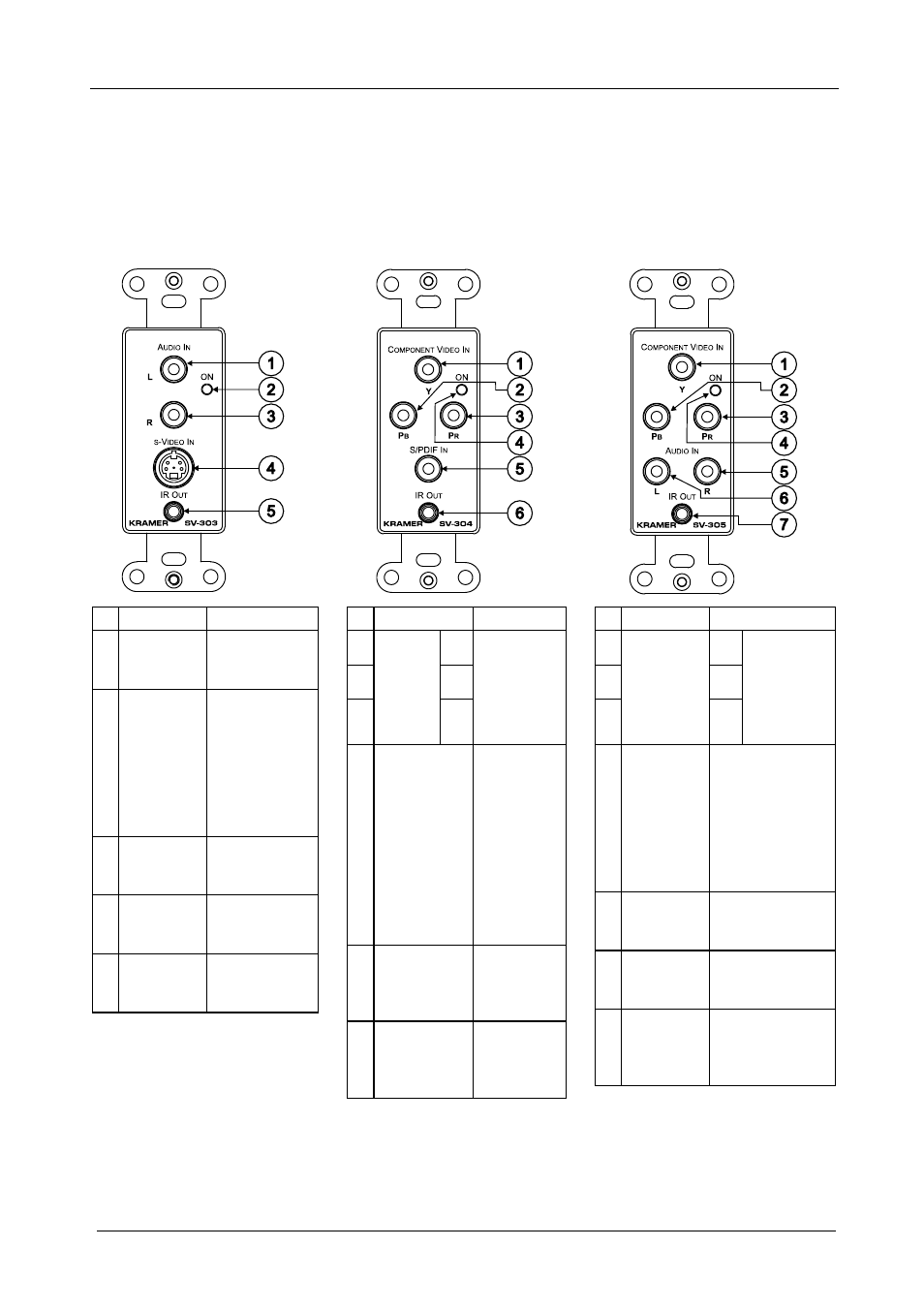
Table 2 and Table 3 define the front and rear views of the
SV-303, SV-304 and
SV-305, respectively:
Table 2: Defining the SV-303, SV-304 and SV-305 (for the U.S.)
SV-303:
SV-304:
SV-305:
# Feature
Function
1 L AUDIO
IN RCA
Connector
Connect to the
left analog
audio source
2 ON LED
Lights in RED
when receiving
power (when
no signal is
detected); lights
in GREEN
when receiving
a signal
3 R AUDIO
IN RCA
Connector
Connect to the
right analog
audio source
4 s-VIDEO IN
4p
Connector
Connect to the
s-Video source
5 IR OUT
3.5mm
Mini Plug
Connect to a
machine via
an IR Emitter
# Feature
Function
1
Y
2
PB
3
C
O
M
P
O
N
E
N
T
V
ID
E
O
IN
R
C
A
C
on
ne
ct
or
s
PR
Connect to
the
component
video
source
4 ON LED
Lights in
RED when
receiving
power (when
no signal is
detected);
lights in
GREEN
when
receiving a
signal
5 S/PDIF IN
RCA
Connector
Connect to
the digital
audio
source
6 IR OUT
3.5mm Mini
Plug
Connect to
a machine
via an IR
Emitter
# Feature
Function
1
Y
2
PB
3
C
O
M
P
O
N
E
N
T
V
ID
E
O
IN
R
C
A
C
on
ne
ct
or
s
PR
Connect to
the
component
video
source
4 ON LED
Lights in RED
when receiving
power (when no
signal is
detected); lights
in GREEN when
receiving a
signal
5 R AUDIO
IN RCA
Connector
Connect to the
right analog
audio source
6 L AUDIO
IN RCA
Connector
Connect to the
left analog audio
source
7 IR OUT
3.5mm
Mini Plug
Connect to a
machine via an
IR Emitter