4 defining the wall plates (for the united states), Defining the wall plates (for the united states) – Kramer Electronics SV-305 User Manual
Page 5
Defining the Wall Plates (for the United States)
3
4 Defining the Wall Plates (for the United States)
Section 4.1 defines the
SV-301 and SV-302, and section 4.2 defines the
SV-303, SV-304 and SV-305.
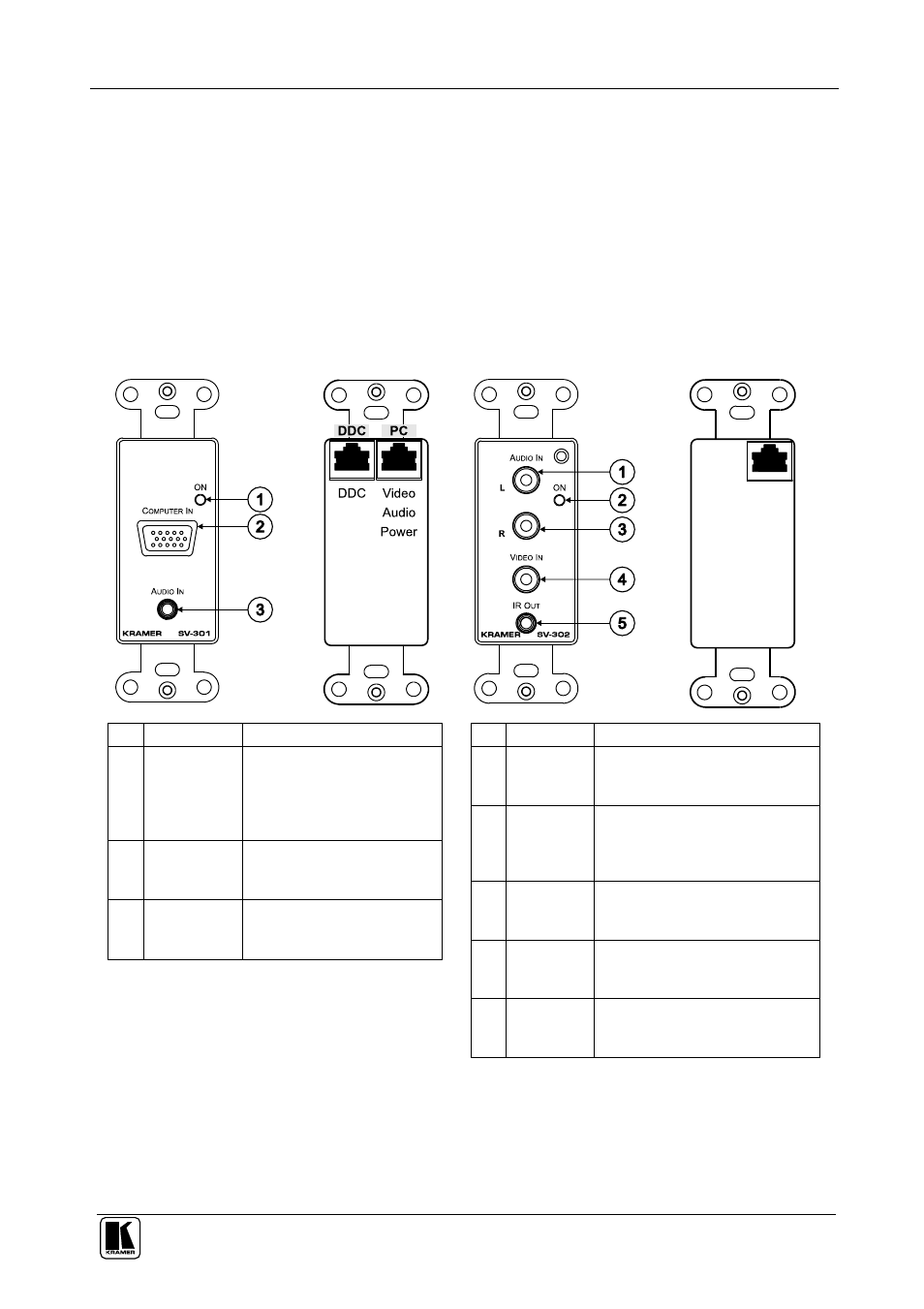
4.1 SV-301 and SV-302 (for the United States)
Table 1 defines the front and rear views of the
SV-301 and SV-302:
Table 1: Defining the SV-301 and SV-302 (for the U.S.)
SV-301:
2 RJ-45 CAT5
Connectors
SV-302
1 RJ-45 CAT5
Connector
#
Feature
Function
1
ON LED
Lights in RED when
receiving power (when no
signal is detected); lights in
GREEN when receiving a
signal
2
COMPUTER
IN 15-pin HD
Connector
Connect to the computer
graphics source
3
AUDIO IN
3.5mm Mini
Plug
Connects to the audio
source
#
Feature
Function
1
L AUDIO
IN RCA
Connector
Connect to the left analog
audio source
2
ON LED
Lights in RED when receiving
power (when no signal is
detected); lights in GREEN
when receiving a signal
3
R AUDIO
IN RCA
Connector
Connect to the right analog
audio source
4
VIDEO IN
RCA
Connector
Connect to the composite video
source
5
IR OUT
3.5mm
Mini Plug
Connect to a machine via an IR
Emitter