Kramer Electronics SV-305 User Manual
Page 12
KRAMER: SIMPLE CREATIVE TECHNOLOGY
Wiring the Rear Panel Connectors
10
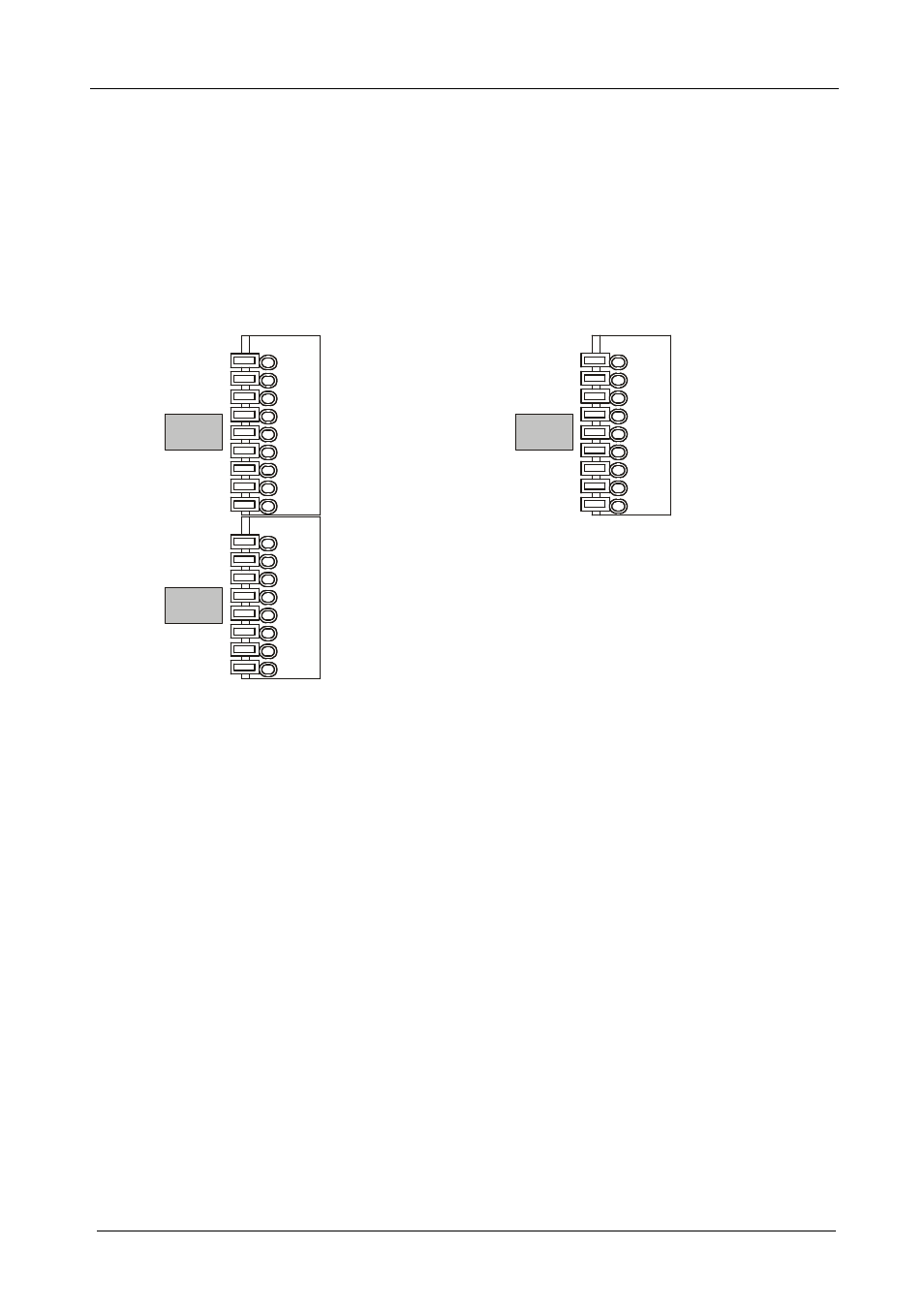
6.2 Wiring the CAT 5 LINE IN / LINE OUT Terminal Block Connectors
The European versions are equipped with an easy plug-in terminal for the CAT
5 cables. Use the color coded sticker on these terminals for proper connection
of the CAT 5 cable.
Table 11 defines the PINOUT of the terminal block connectors:
Table 11: Terminal Block Connector PINOUT (for Europe)
SV-301, SV-304, SV-305 Rear Panel PINOUT
SV-302, SV-303 Rear Panel PINOUT
Brown
Brown
Gnd
Brown / White
Brown / White
Green
Green
Blue / White
Blue / White
Blue
Blue
Green / White
Green / White
Orange
Orange
Orange / White
Orange / White
DDC
PC
Brown
Gnd
Brown / White
Green
Blue / White
Blue
Green / White
Orange
Orange / White
Video
Notes:
The “PC” section has 9 PINs; the “DDC” section has 8 PINs. Only use the
connector clips to remove the wires, not when inserting them
Each wire protrudes 9mm in length from the plastic casing so that it can be
easily connected. To prevent the wires crossing, be sure that each wire is
completely inserted
With STP cable, the Gnd pin is used for shielding. For the DDC channel,
shielding is not needed, but if desired, connect the GND pin of the PC