5 installing the rc-8ir universal room controller, Installing the rc-8ir universal room controller, Figure 3: rc-8ir rear panel – Kramer Electronics RC-8iR User Manual
Page 8: Table 3: rc-8ir and rear panel features, Figure 3 and table 3 define the rc-8ir rear panel
Installing the RC-8IR Universal Room Controller
5
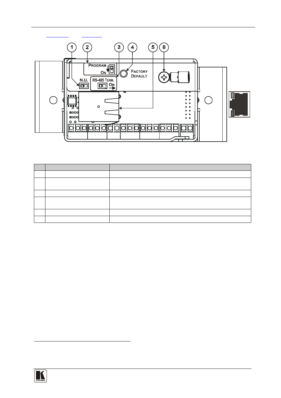
Figure 3: RC-8IR Rear Panel
Table 3: RC-8IR and Rear Panel Features
#
Feature
Function
1
N.U Switch
Not used
2
PROGRAM Switch
Switch to OFF for normal operation;
Switch to ON for firmware upgrade
3
RS-485 TERM. Switch
Switch to ON for RS-485 line termination
4
FACTORY DEFAULT Button Press to return to the factory default settings, including all the
configured buttons and the network settings
5
Ethernet Port
Connects to a PC or other controller through computer networking
6
Grounding Screw
Connect to grounding wire
5 Installing the RC-8IR Universal Room Controller
This section describes the installation of the RC-8IR and includes:
•
Setting up the labels on the buttons, according to your specific
requirements
•
Mounting the RC-8IR device to the wall
•
Installing the button caps
•
Mounting the faceplate
•
Setting of the device
1 Including the factory default IP number: 192.168.1.39 (an IP number is a device's numerical address as expressed in the
format specified in the Internet Protocol)
2 It is recommended to place labels before mounting the faceplate