Figure 2: rc-8ir right side panel, Table 2: rc-8ir right side panel features, Table 2 – Kramer Electronics RC-8iR User Manual
Page 7
KRAMER: SIMPLE CREATIVE TECHNOLOGY
Your Universal Room Controller
4
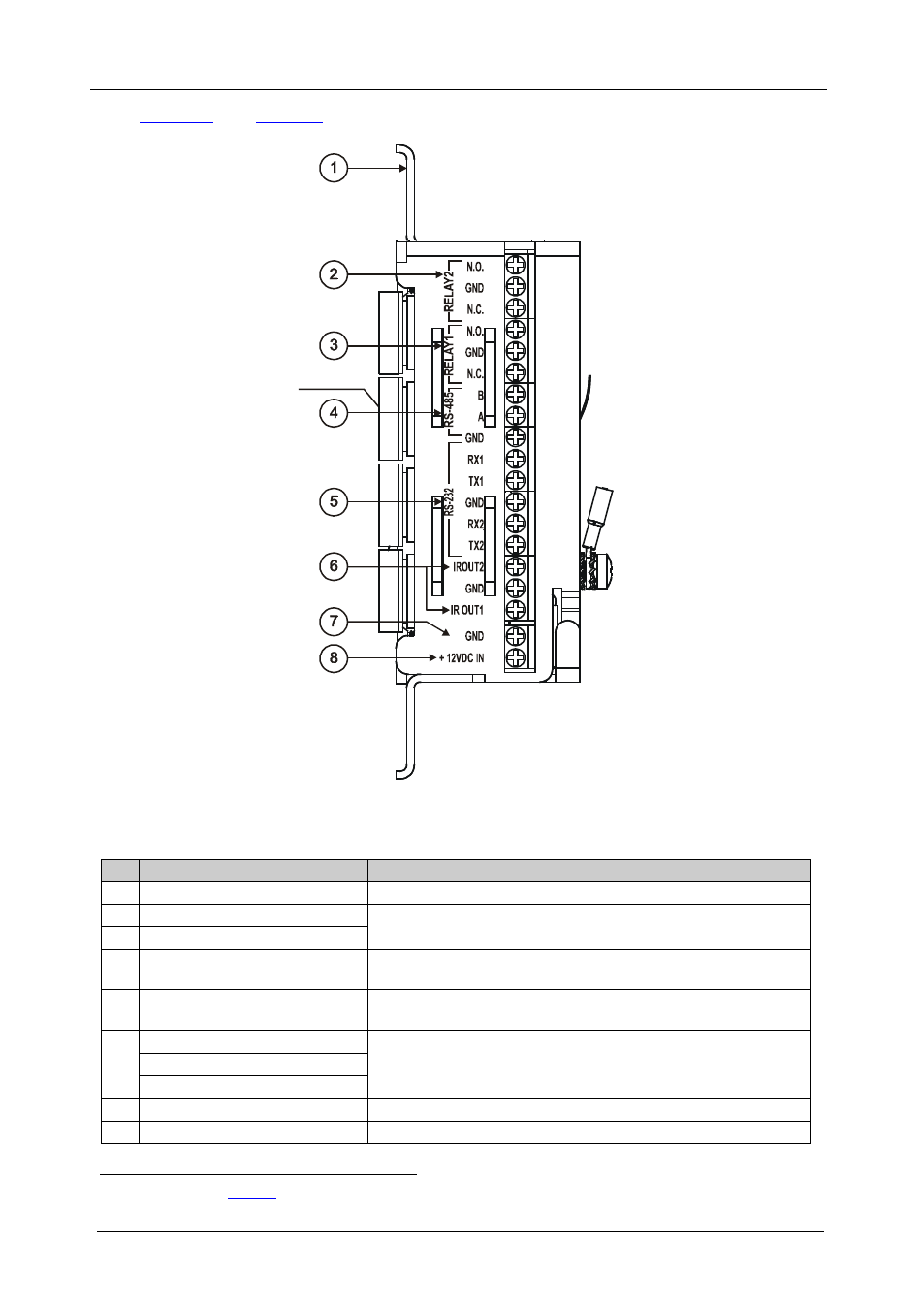
define the RC-8IR right side panel:
Front Panel
Buttons
Figure 2: RC-8IR Right Side Panel
Table 2: RC-8IR Right Side Panel Features
#
Feature
Function
1
Housing and Faceplate Support Device housing supports the faceplate
2
RELAY2
Connect each relay to a room item (such as lighting, screen
settings, blinds, and so on)
3
RELAY1
4
RS-485 Terminal Block
Connector
Connect to the RS-485 detachable terminal block on a switcher
or PC
5
RS-232 Terminal Block
Connector (1 and 2)
Connect to the RS-232 connector on the A/V equipment or a PC or
other Serial Controller
6
IR OUT1 PIN
GND PIN
Connect to an IR emitter cable
IR OUT2 PIN
7
GND PIN
Connects (-) to the Ground
8
+12VDC IN PIN
Connects (+) to the connector for powering the unit
1 See the examples in
- VM-114H (22 pages)
- VM-114H2C (25 pages)
- VM-114H4C (23 pages)
- VS-81ETH (27 pages)
- VS-81ETH (41 pages)
- VM-9T (13 pages)
- VP-12NHD (15 pages)
- VP-5R (20 pages)
- VP-6A (15 pages)
- PT-5R/T (13 pages)
- TP-102HD (13 pages)
- TP-104HD (33 pages)
- TP-112HD (13 pages)
- TP-114 (13 pages)
- TP-202 (15 pages)
- TP-205A (15 pages)
- TP-210 (14 pages)
- TP-210A (15 pages)
- tp-219hd (16 pages)
- TP-305A (15 pages)
- TP-310A (18 pages)
- TP-410 (34 pages)
- VM-1H4C (17 pages)
- VP-200xlT (31 pages)
- VP-300THD (12 pages)
- VPM-2 (42 pages)
- SI-1VGA (2 pages)
- SID-DP (2 pages)
- SID-DVI (2 pages)
- SID-H (2 pages)
- SID-VGA (2 pages)
- SID-X1 (2 pages)
- SID-X1 (23 pages)
- SID-X1N (23 pages)
- SID-X2N (31 pages)
- SID-X3N (22 pages)
- 622R (17 pages)
- VS-169TP (7 pages)
- VS-169TP (45 pages)
- WSI-1VGA (2 pages)
- TP-107AV (32 pages)
- RC-5B2 (137 pages)
- WP-500 (2 pages)
- SV-552 (22 pages)
- WP-501 (16 pages)