Table 4 – Kramer Electronics RC-8iR User Manual
Page 12
Using the RC-8IR Universal Room Controller
9
Table 4: Connection Scheme (for the example in
This connector:
Controls:
RELAY2
The lights
RELAY1
The screen
RS-485 Terminal Block Connector
A power amplifier (and speakers)
RS-232 (TX1, RX1) Terminal Block Connector
A projector
IR OUT1 PIN
A DVD player
IR OUT2 PIN
A video player
Ethernet
The RC-8IR via a remote control PC
A laptop is connected to the projector
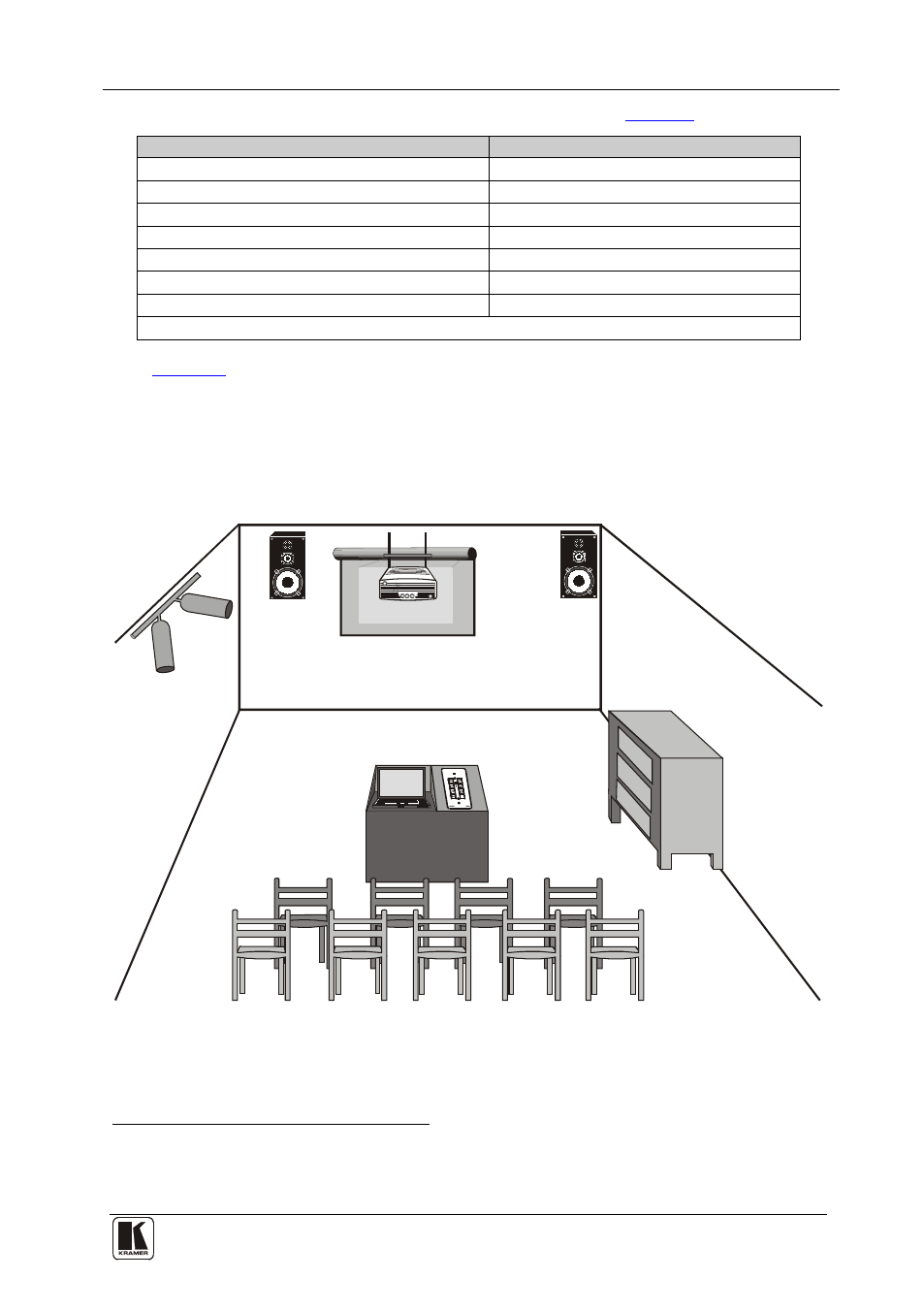
shows the RC-8IR built into a podium that is located in a lecture
auditorium. An overhead projector and screen, speakers, lights; and a cabinet
with a VCR, a DVD and an amplifier inside, are all controlled via the
RC-8IR. The presenter’s laptop is located on the podium, next to where the
RC-8IR is mounted. It is also controlled by the RC-8IR and is used for
presentations, slide shows and so on.
VCR
DVD
Amplifier
Figure 9: Example of a Typical RC-8IR Setup in the Lecture Auditorium
1 The second RS-232 port can be used to control another A/V unit or an LCD
2 Connected via the IR emitter cable. IR OUT1 and IR OUT2 can each be connected to identical machines and still be
controlled separately