Kramer Electronics RC-8000 User Manual
Page 26
Connecting Your Matrix Switchers
23
6.5 Connecting a Component
1
, Y/C, RGBS or RGBHV Switcher
A component
2
switcher consists of three
VS-88V switchers, interconnected as
one group, with one of the switchers set as the Master. A component switcher
can function in the IN SYSTEM or standalone mode. Similarly, you can
configure two
VS-88V switchers for Y/C (s-Video), four VS-88V switchers
for RGBS or five
VS-88V switchers for RGBHV.
To set the
VS-88V switchers in the group to operate as a single component
switcher, do the following with every switcher in the group:
Set the same MACHINE # for each switcher (for example, MACHINE # 2)
Set dipswitch # 5 OFF
Set dipswitch # 6 OFF (
except on the Master, set Dipswitch # 6 ON)
Except for the Master (whose LEDs illuminate and front panel controls remain
unlocked), the LEDs on all switchers in the group are dimmed, and their front
panel controls are locked
3
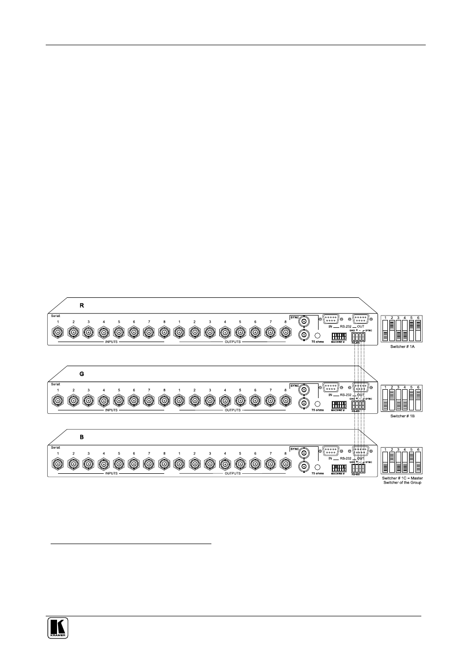
Figure 9 illustrates a component switcher that consists of a group of 3
VS-88V switchers:
Figure 9: Component Switcher: VS-88V Group Connection
1 For RGB or YUV (Y, B-Y, R-Y)
2 Video signal in component form offers the highest professional video quality, superior to composite or s-Video
3 After initially powering up the component switcher, if some of its switchers remain in a different status, press the ALL
button followed by the OFF button on the Master to reset all the connections prior to normal operation