Your matrix switchers – Kramer Electronics RC-8000 User Manual
Page 17
KRAMER: SIMPLE CREATIVE TECHNOLOGY
Your Matrix Switchers
14
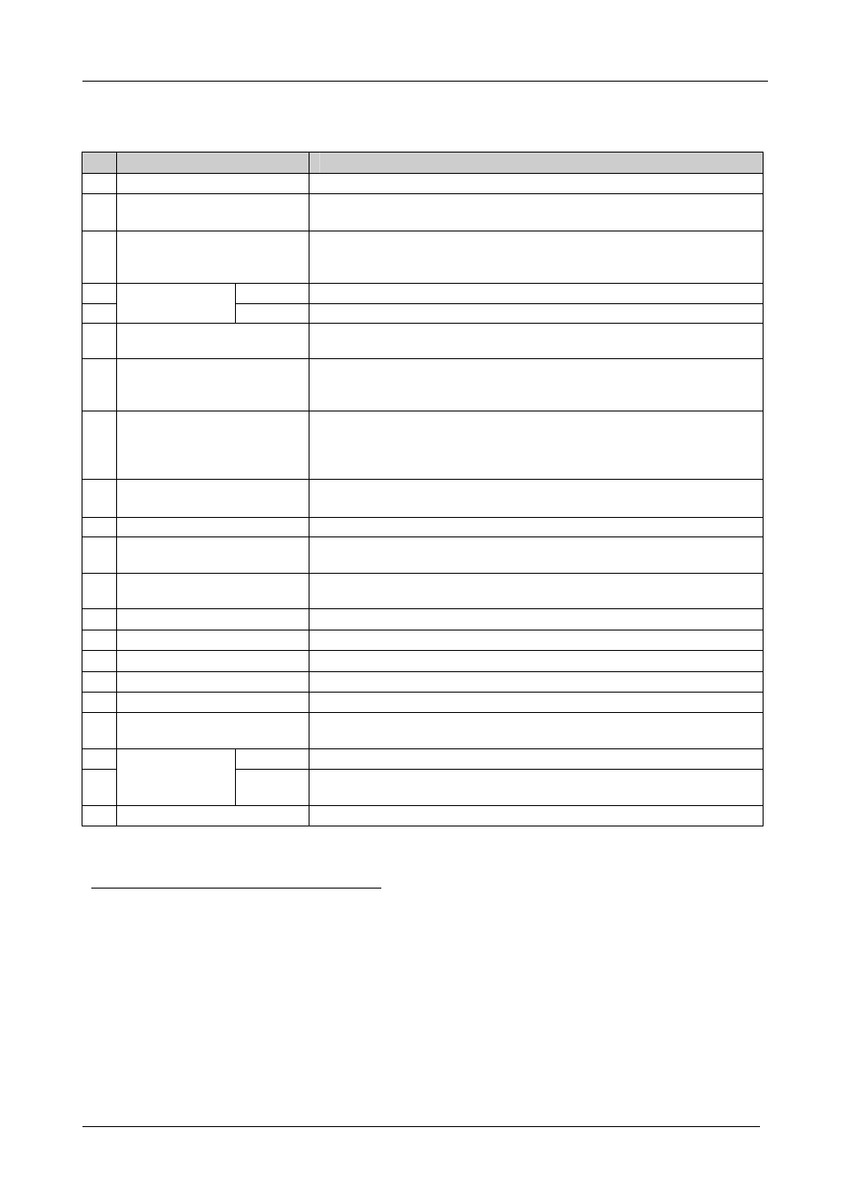
Table 4 defines the features and functions of the
SD-7588V:
Table 4: SD-7588V 8x8 SDI Matrix Switcher Features
#
Feature
Function
1
Power Switch
Illuminated switch supplying power to the unit
2
ALL Button
(ALL= All Outputs)
Pressing ALL before pressing an INPUT button, connects that input to all
outputs
1
3
OFF Button
(OFF= All Inputs)
Pressing OFF after pressing an OUTPUT button disconnects that output
from the inputs. To turn off the connections, press the ALL button and then
the OFF button
4
OUT
Select the output to which the input is switched
5
SELECT Buttons
IN
Select the input to switch to the output
6
STO Button
Pressing STO (STORE) followed by an output button stores the current
setting (refer to section 8.2.1)
2
7
RCL Button
Pressing the RCL (Recall) button and the corresponding OUT key recalls a
setup. Press the RCL button again to implement the new status (refer to
section 8.2.2)
8
IN SYSTEM Button
Pressing IN SYSTEM twice
3
, switches between the Standalone mode (in
which the switcher implements any action independently from the others)
and the In System mode (in which all switchers implement the same action
simultaneously)
9
TAKE Button
(TAKE = CONFIRM)
Pressing TAKE toggles the mode between the CONFIRM mode
4
and the
AT ONCE mode (user confirmation per action is unnecessary)
10 OUTPUT Labels
Identifies a connection between the output and the input shown below it
11 INPUT Status Display
Displays the selected input switched to the output (marked above each
input)
12 INPUT STATUS LEDs
Illuminate when the input signal is presented on a corresponding line and
complies with the SDI standard
13 INPUT BNC Connectors
Connect to the composite video sources (from 1 to 8)
14 OUTPUT BNC Connectors
Connect to the composite video acceptors (from 1 to 8)
15 SYNC BNC Connectors
For looping to external video sync input
16 75 OHMS Button
Controls loop termination
5
17 MACHINE #
Dipswitches for setup of the machine number (refer to section 6.1)
18 RS-485 Connector
RS-485 detachable terminal block port. Pins # 1 to # 3 are for RS 485 and
pin # 4 is for vertical sync distribution
6
19
IN
Connects to PC or Remote Controller
7
RS-232
9-pin D-sub
Connectors
OUT
Connects to the RS-232 IN 9-pin D-sub port of the next unit in the daisy-
chain connection
8
20 Power Connector with Fuse AC connector enabling power supply to the unit
1 For example, press ALL and then Input button # 2 to connect input # 2 to all the outputs
2 For example, press STO and then the Output button # 3 to store in Setup # 3
3 After pressing IN SYSTEM once, it blinks
4 When in Confirm mode, the TAKE button illuminates
5 Push in to terminate the SYNC line. Push out when the line extends to another unit
6 The 88 Series RS-485 connector has 4 pins, and the Remote Controller RS-485 connector has just 3 pins
7 If the unit is not the first unit in the line, connects to the RS-232 OUT 9-pin D-sub port of the previous unit in the line
8 If the unit is the final unit in the daisy-chain connection, no termination is required