Your matrix switchers – Kramer Electronics RC-8000 User Manual
Page 20
Your Matrix Switchers
17
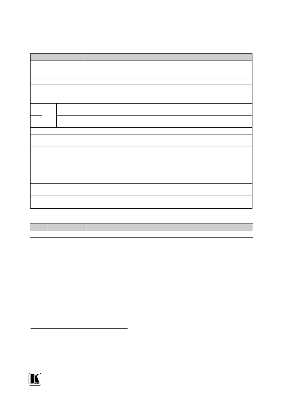
Table 5 and Table 6 define the features and functions of the
RC-8000:
Table 5: RC-8000 Remote Controller Top Panel Features
#
Feature
Function
1
MACHINE IN
SYSTEM Buttons
Enable toggle between the standalone and the IN SYSTEM modes of any
switcher, and viewing the status and control of the corresponding switcher
1
(from
1 to 8)
2
INPUT Buttons
Select the input to switch to the output (from 1 to 8)
3
Comm. Error LED
The Comm. Error red LED illuminates when a connection between the remote
controller and a switcher fails
2
4
OUTPUT Buttons
Select the output to which the input is switched (from 1 to 8)
5
OUTPUT
labels
Identifies a connection between the output and the input shown below it
6
S
TA
TU
S
INPUT
Display
Displays the selected input switched to the output (marked above each input)
7
POWER LED (green) Illuminates when power is activated
8
TAKE Button
(TAKE = CONFIRM)
Pressing TAKE toggles the mode between the CONFIRM mode
3
and the AT
ONCE mode (user confirmation per action is unnecessary)
9
STO Button
Pressing STO (STORE) followed by an output button stores the current setting
(refer to section 8.2.1)
10 RCL Button
Pressing the RCL (Recall) button and the corresponding OUT key recalls a setup.
Press the RCL button again to implement the new status (refer to section 8.2.2)
11 ALL Button
(ALL= All Outputs)
Pressing ALL before pressing an INPUT button, connects that input to all outputs
4
12 Three Screws
Removing the three screws separates the base platform. By drilling three holes in
the desktop you can screw the remote controller directly in place
13 OFF Button
(OFF= All Inputs)
Pressing OFF after pressing an OUTPUT button disconnects that output from the
inputs. To turn off the connections, press the ALL button and then the OFF button
Table 6: RC-8000 Remote Controller Rear Panel Features
#
Feature
Function
1
Power Socket
+12V DC connector enabling power supply to the unit
2
RS-485 Connector
RS-485 detachable terminal block port
1 Refer to section 7
2 For example, the switcher is not connected at all, or connected, but without power
3 When in Confirm mode, the TAKE button illuminates
4 For example, press ALL and then Input button # 2 to connect that input to all outputs