Figure 2: rc-62 room controller rear panel, Table 3: rc-62 rear panel features, Figure 2 – Kramer Electronics RC-63DL User Manual
Page 9: Table 3
Installing the Room Controller
5
5
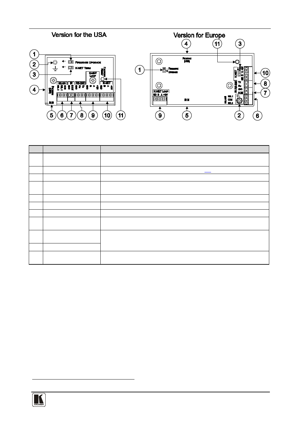
Figure 2: RC-62 Room Controller Rear Panel
Table 3: RC-62 Rear Panel Features
#
Feature
Function
1
FIRMWARE UPGRADE
Switch
For technical support use only
2
Grounding Screw
Connect to grounding wire (optional), see section
3
K-NET TERM Switch
For line termination
4
PROGRAM (USB)
Connector
Connect to a computer for unit configuration
5
IR IN Receiver
Receives IR remote commands
6
RELAYS Connections
Connect to room items (such as lighting, screen settings, blinds, and so on)
7
IR Connections
Control a machine via an IR Emitter
8
RS-232 Connections
Connect to the RS-232 connector on the A/V equipment or a PC or other Serial
Controller
9
K-NET LOOP
Connections
On K-NET and K-NET LOOP, PIN GND is for the Ground connection
10
; PIN
B (-) and PIN A (+) are for RS-485, and PIN +12V is for powering the unit
K-NET Connections
11
FACTORY RESET
Button
Press to revert to the default settings, including all the configured buttons
1 The ground connection is sometimes connected to the shield of the RS-485 cable (in most applications, it is not connected)