Figure 8 a nd table 10 d efine – Kramer Electronics RC-63DL User Manual
Page 16
KRAMER: SIMPLE CREATIVE TECHNOLOGY
Using Your Room Controller
12
summarizes the room controller functions and characteristics.
Table 9: Room Controller Functions and Characteristics
Master
Standalone
Auxiliary
K-NET Connector(s)
Connects to up to
two auxiliary devices
–
Connects to the master
device
Connects to controlled machines Yes
Yes
Yes
Requires power supply
Yes
Yes
No, receives power from
the Master Controller
Requires Programming
Yes
Yes
No, receives commands
from the Master controller
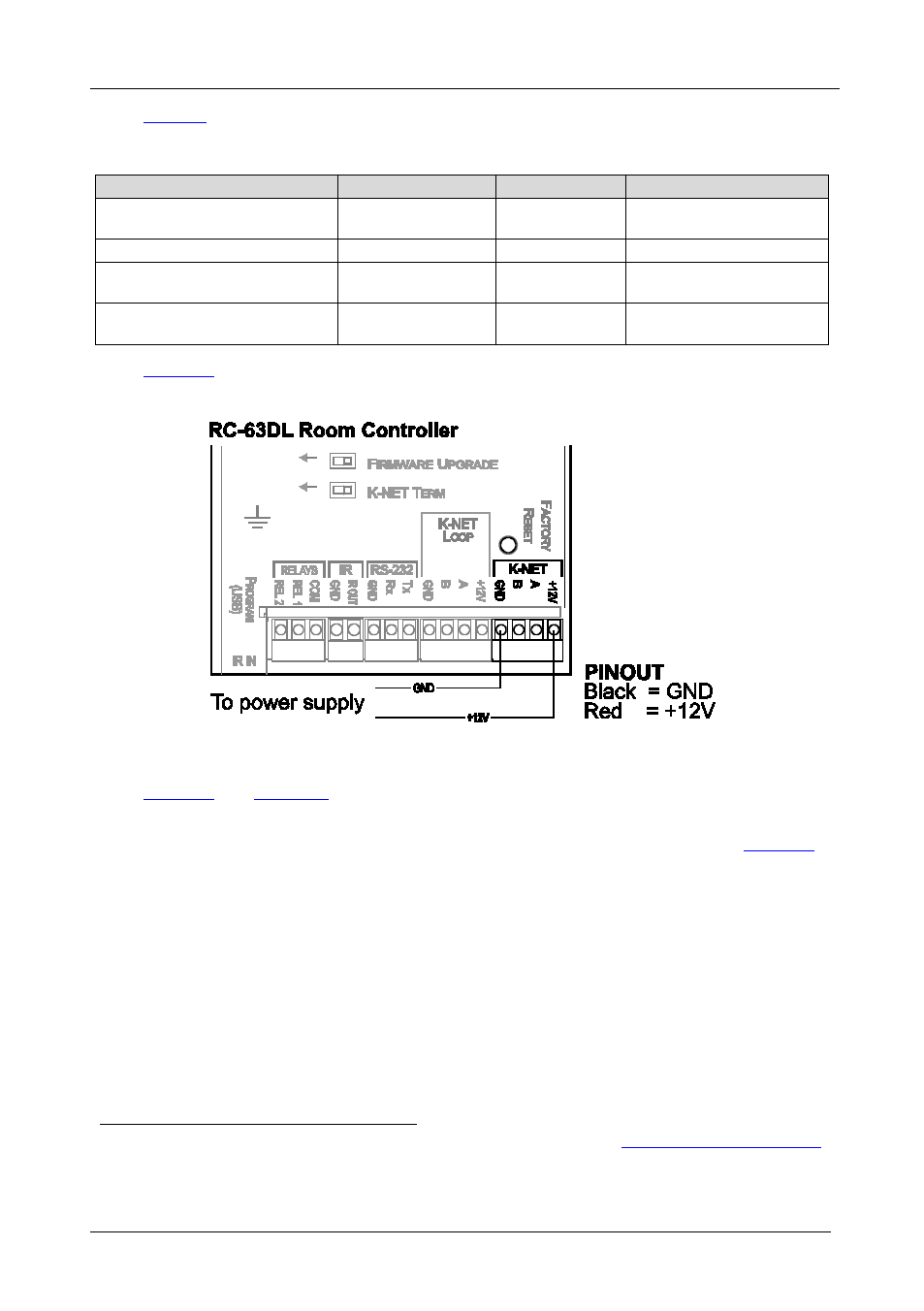
defines the power supply pinout for Master and standalone room
controllers:
Figure 7: RC-63D Master/Standalone Power Supply Pinout
and
define
a standalone room controller. If the room controller
is configured to be a Master room controller, up to two auxiliary devices can be
connected via the two K-NET terminal block connectors (not shown in
1 Refer to the separate K-Config online configuration software technical documentation at
http://www.kramerelectronics.com
2 Your room controller was installed and configured to suit your specific requirements. This example describes how to setup
one of an unlimited number of available setups for the system