4 grounding the room controller, Grounding the room controller, Figure 13: grounding connection components – Kramer Electronics RC-63DL User Manual
Page 22: Table 12: grounding component descriptions
KRAMER: SIMPLE CREATIVE TECHNOLOGY
Customizing the Controllers' Buttons and Labels
18
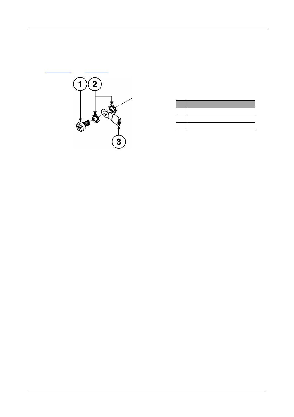
6.4 Grounding the Room Controller
The grounding screw is used to earth the chassis of the unit to the building ground
preventing static electricity from impacting the performance of the unit.
define the grounding screw components.
Figure 13: Grounding Connection
Components
Table 12: Grounding Component
Descriptions
#
Component Description
1
M3X6 screw
2
1/8" Toothed Lock Washer
3
M3 Ring Tongue Terminal
To ground the room controller:
1. Connect the Ring Tongue terminal to the building grounding point wire
(it is recommended to use a green-yellow AWG#18 (0.82mm
2
) wire,
crimped with a proper hand-tool).
2. Insert the M3x6 screw through the toothed lock washers and the tongue
terminal in the order shown above.
3. Insert the M3x6 screw (with the two toothed lock washers and ring
tongue terminal) into the grounding screw hole and tighten the screw.