Figure 8, Table 10 – Kramer Electronics RC-63DL User Manual
Page 17
Using Your Room Controller
13
13
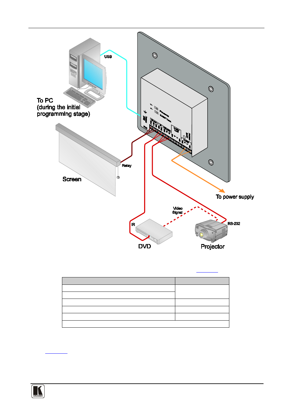
Figure 8: Example of a Typical Standalone RC-63DL Configuration
Table 10: Connection Scheme (for the example in
This connector:
Connects to:
REL 1
The screen
REL 2
IR OUT and GND PINs
A DVD player
RS-232 (TX, RX) Terminal Block Connector
A projector
+12V and GND
A power supply unit
A PC is connected via the USB connector for setup of the room controller
When the room controller is used as a system controller for the SummitView™
system via the proprietary communication channel K-NET, as illustrated in
•
It requires only a K-NET connection to the Master device (for example, the
Kramer SV-551 or SV-552 SummitView™ Processor / Switcher)
•
A power supply unit is not required