Your vs-88hd 8x8 sd/hd-sdi matrix switcher – Kramer Electronics VS-88HD User Manual
Page 7
Your VS-88HD 8x8 SD/HD-SDI Matrix Switcher
5
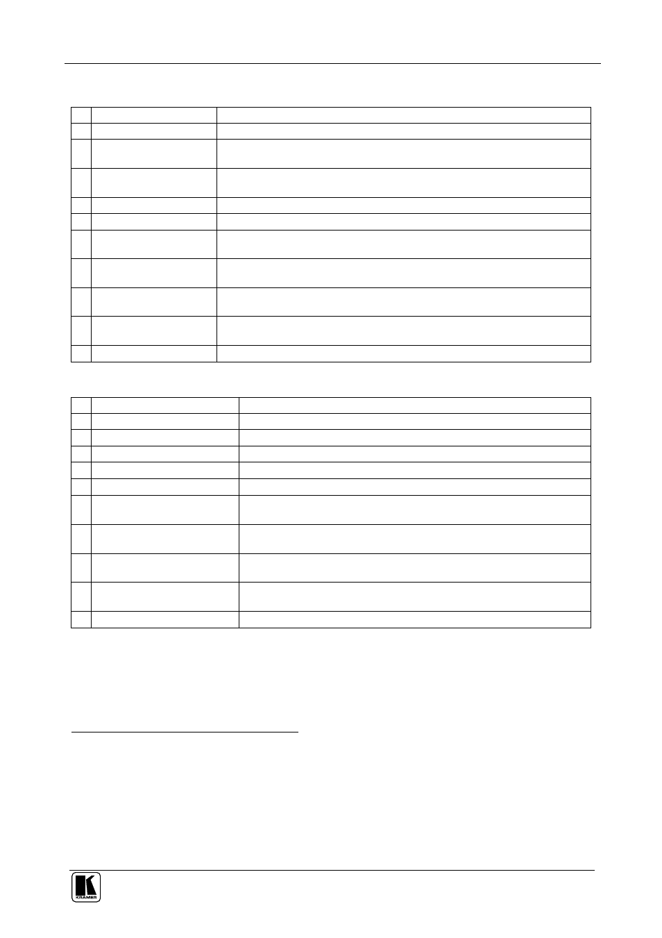
Table 1: Front Panel VS-88HD 8x8 SD/HD-SDI Matrix Switcher
# Feature
Function
1
POWER
Switch
Illuminated switch for turning the unit ON or OFF
2
OFF
Button
An
OFF
-
OUT
combination disconnects that output from the inputs; an
OFF
-
ALL
combination disconnects all the outputs
3
ALL
Button
Pressing
ALL
followed by an
INPUT
button, connects that input to all
outputs
1
4
IN SELECT
Buttons
Select the input to switch to the output
5
OUT SELECT
Buttons Select the output to which the input is switched
6
STO
(STORE) Button
Pressing STO followed by an INPUT / OUTPUT button stores the current
setting
2
7
RCL
(
RECALL
) Button
Pressing the
RCL
button and the corresponding INPUT / OUTPUT key
recalls a setup from the non-volatile memory
8
TAKE
Button
Pressing
TAKE
toggles the mode between the
CONFIRM
mode
3
and the
AT ONCE
mode (user confirmation per action is unnecessary)
9 7-segment
Display
Displays the selected input switched to the output (marked above each
input)
10
INPUT STATUS
LEDs
Lights when the input signal complies with the SDI standard
Table 2: Rear Panel VS-88HD 8x8 SD/HD-SDI Matrix Switcher
# Feature
Function
11
INPUT
BNC Connectors
Connect to the serial digital video sources
12
OUTPUT
BNC Connectors
Connect to the serial digital video acceptors
13
LOOP
BNC Connector
Connect to the Genlock connector of the next unit in the line
14
SYNC
BNC Connector
Connect to the Genlock source
15 75 TERM Button
Press to terminate the Genlock source (75 ) or release for looping
4
16
RS-232 IN
9-pin D-sub
Female Port
Connects to the PC or the Remote Controller
5
17
RS-232 OUT
9-pin D-sub
Male Port
Connects to the RS-232 IN
DB 9F port of the next unit in the
daisy-chain connection
18 MACHINE # DIP-switches
Dipswitches for setup of the unit (1, 2, 3 and 4 are for setting the
Machine #; 8 is for RS 485 Termination)
19
RS-485
Detachable
Terminal Block Port
The SYNC and the G PINs are for vertical sync and the ground
6
connection respectively; pins A (+) and B (-) are for RS-485
20 Power Connector with Fuse AC connector enabling power supply to the unit
1 For example, press ALL and then Input button # 2 to connect input # 2 to all the outputs
2 For example, press STO and then the Output button # 3 to store in Setup # 3
3 When in Confirm mode, the TAKE button illuminates
4 Push in to terminate the input. Release when the input extends to another unit
5 Via a null-modem connection
6 The ground connection is sometimes connected to the shield of the RS-485 cable. In most applications, the ground is not
connected