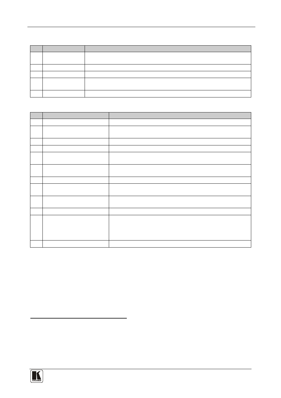
Table 1, Table 2, Your vs-41hd 4x1 hd/sd-sdi switcher / da – Kramer Electronics VS-41HD User Manual
Page 8
Your VS-41HD 4x1 HD/SD-SDI Switcher / DA
5
5
Table 1: Front Panel VS-41HD 4x1 HD/SD-SDI Switcher / DA
#
Feature
Function
1
IR Receiver
The red LED is illuminated when receiving signals from the infra-red remote
control transmitter
2
POWER Switch
Illuminated switch for turning the unit ON or OFF
3
OFF Button
Press to disconnect the outputs
4
INPUT SELECTOR
Buttons
Select the input to switch to the output
Use to set the resolution when switching genlocked video signals (see section 6.4)
5
LOCK Button
Disengages the front panel buttons
Table 2: Rear Panel VS-41HD 4x1 HD/SD-SDI Switcher / DA
#
Feature
Function
6
GENLOCK BNC Connector
Connect to the Genlock source
7
TERM Button
Press to terminate the Genlock source (75
Ω) or release for
looping
8
LOOP BNC Connector
Connect to the GENLOCK connector of the next unit in the line
9
INPUTS BNC Connectors
Connect to the serial digital video sources (from 1 to 4)
10
OUTPUTS BNC Connectors
Connect the two identical outputs to serial digital video acceptors
(1 and 2)
11
RS-485 Detachable Terminal
Block Port
Pin G is for the Ground connection
12
; pins B (-) and A (+) are for RS-485
RS-232 DB 9F Port
Connects to the PC or the Remote Controller
13
C.C. REMOTE Terminal
Block Connector
Connect to contact closure switches
14
ETHERNET Connector
Connects to the PC or other Serial Controller through computer
networking
15
MACH. ID Dipswitches
Dipswitches for setting the machine ID number
16
ETH FACTORY RESET
Button
Press to reset to factory default definitions
IP number
− 192.168.1.39
:
Mask – 255.255.255.0
Gateway – 192.168.1.1
17
Power Connector with Fuse
AC connector enabling power supply to the unit
1 Extending the input to another unit
2 The ground connection is sometimes connected to the shield of the RS-485 cable. In most applications, the ground is not
connected
3 Via a null-modem connection
4 First disconnect the power cord and then connect it again while pressing the ETH Factory Reset button. The unit will power
up and load its memory with the factory default definitions