Table 6: instruction codes for protocol 2000, Kramer protocol 2000 – Kramer Electronics VS-41HD User Manual
Page 20
Kramer Protocol 2000
17
17
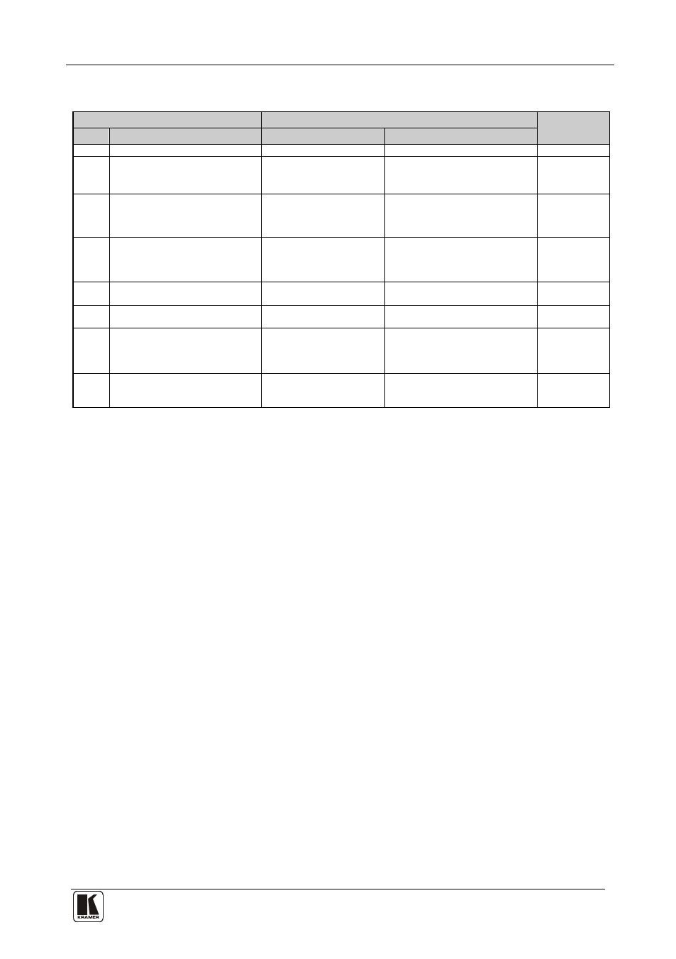
Table 6: Instruction Codes for Protocol 2000
Note: All values in the table are decimal, unless otherwise stated.
INSTRUCTION
DEFINITION FOR SPECIFIC INSTRUCTION
NOTE
#
DESCRIPTION
INPUT
OUTPUT
0
RESET VIDEO
0
0
1
1
SWITCH VIDEO
Set equal to video input
which is to be switched
(0 = disconnect)
Set equal to video output which is
to be switched
(0 = to all the outputs)
2,
5
REQUEST STATUS OF A
VIDEO OUTPUT
0
Equal to output number whose
status is read
4
16
ERROR / BUSY
0
0 - error
1 - invalid instruction
2 - out of range
9
30
LOCK FRONT PANEL
0 - Panel unlocked
1 - Panel locked
0
2
31
REQUEST WHETHER PANEL
IS LOCKED
0
0
16
61
IDENTIFY MACHINE
1 - video machine name
3 - video software version
0 - Request first 4 digits
1 - Request first suffix
10 - Request first prefix
13
62
DEFINE MACHINE
1 - number of inputs
2 - number of outputs
3 - number of setups
1 - for video
14
NOTES on the above table:
NOTE 1 - When the master switcher is reset, (e.g. when it is turned on), the reset code is sent to the PC. If this code is sent to
the switchers, it will reset according to the present power-down settings.
NOTE 2 - These are bi-directional definitions. That is, if the switcher receives the code, it will perform the instruction; and if
the instruction is performed (due to a keystroke operation on the front panel), then these codes are sent. For example, if the
HEX code
01
85
88
83
was sent from the PC, then the switcher (machine 3) will switch input 5 to output 8. If the user switched input 1 to output 7
via the front panel keypad, then the switcher will send HEX codes:
41
81
87
83
to the PC.
When the PC sends one of the commands in this group to the switcher, then, if the instruction is valid, the switcher replies by
sending to the PC the same four bytes that it was sent (except for the first byte, where the DESTINATION bit is set high).
NOTE 4 - The reply to a "REQUEST" instruction is as follows: the same instruction and INPUT codes as were sent are
returned, and the OUTPUT is assigned the value of the requested parameter. For example, if the present status of a Video
Output 1 is 3, then the reply to the HEX code
05
80
81
81
would be HEX codes
45
80
83
81
NOTE 9 - An error code is returned to the PC if an invalid instruction code was sent to the switcher, or if a parameter
associated with the instruction is out of range. This code is also returned to the PC if an RS-232 instruction is sent while the
machine is being programmed via the front panel. Reception of this code by the switcher is not valid.
NOTE 13 - This is a request to identify the switcher/s in the system. If the OUTPUT is set as 0, and the INPUT is set as 1, 2,
5 or 7, the machine will send its name. The reply is the decimal value of the INPUT and OUTPUT. For example, for a 2216,
the reply to the request to send the audio machine name would be (HEX codes):
7D
96
90
81 (i.e. 128dec+ 22dec for 2nd byte, and 128dec+ 16dec for 3rd byte).
If the request for identification is sent with the INPUT set as 3 or 4, the appropriate machine will send its software version
number. Again, the reply would be the decimal value of the INPUT and OUTPUT - the INPUT representing the number in
front of the decimal point, and the OUTPUT representing the number after it. For example, for version 3.5, the reply to the
request to send the version number would be (HEX codes):
7D
83
85
81 (i.e. 128dec+ 3dec for 2nd byte, 128dec+ 5dec for 3rd byte).