Figure 1: vs-21hdcp-ir 2x1 dvi switcher – Kramer Electronics VS-21HDCP-IR User Manual
Page 8
VS-21HDCP-IR - Overview
5
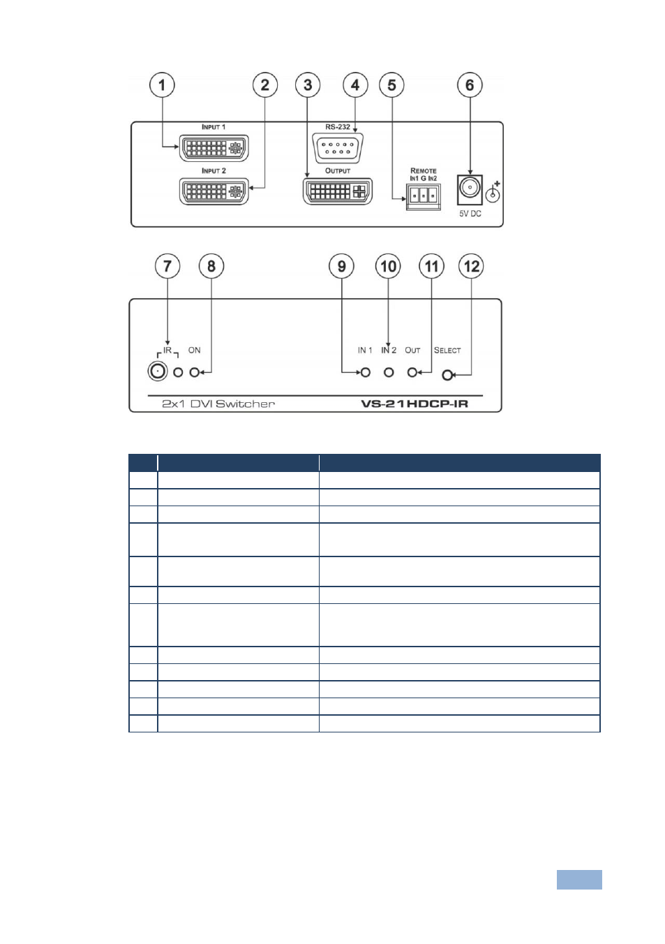
Figure 1: VS-21HDCP-IR 2x1 DVI Switcher
#
Feature
Function
1
INPUT 1 DVI Connector
Connect to the DVI source 1
2
INPUT 2 DVI Connector
Connect to the DVI source 2
3
OUTPUT DVI Connector
Connect to the DVI acceptor
4
RS-232 9-pin D-sub
Connector
Connects to the PC or Serial Controller
No Null-modem adapter/Connector is required
5
REMOTE Terminal Block
Connectors
Connect to a contact closure switch (see Section
6
5V DC
+5V DC connector for powering the unit
7
Remote IR Receiver Window
and LED
Receives signals from the infrared remote control
transmitter and the yellow LED lights when receiving
signals from the infrared remote control transmitter
8
ON LED (Green)
Lights when receiving power
9
IN 1 LED (Green)
Lights when input 1 is selected
10
IN 2 LED (Green)
Lights when input 2 is selected
11
OUT LED (Green)
Lights when the output is connected
12
SELECT Switch
Press to toggle between selecting input 1 and input 2