3 controlling the vp-61xl, 1 dip switches, 2 the "reply" option – Kramer Electronics VP-61xl User Manual
Page 10
KRAMER ELECTRONICS LTD.
9
8.3
Controlling the VP-61xl
The
VP-61xl switcher can be controlled by the following methods:
1. By touch buttons on the front panel.
2. By any RS-232 controller such as a PC.
8.3.1
DIP Switches
The
VP-61xl selects one of 6 VGA/XGA/Audio sources.
The DIP switch (see Table 2) on the rear panel is used when the switcher is
operated via the RS-232 connector or when it is interconnected with other
switchers. These switches allow proper configuration of the control signals
received/transmitted through the RS-232 control port. The
VP-61xl allows
master/slave configurations so that the switchers may operate independently, or in
conjunction with each other.
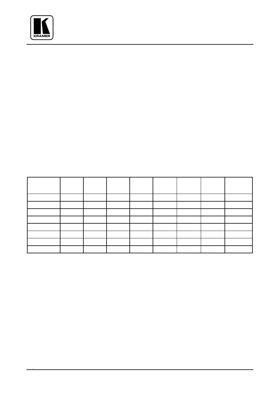
Table 2: DIP Switch Settings
PROGRAM
ADDRESS
Machine
#
1
2
3
4
5
6
7
8
1 (Master) ON
OFF
ON
ON
OFF
OFF
OFF
OFF
2 (Slave)
OFF
OFF
OFF
ON
OFF
OFF
OFF
ON
3 (Slave)
OFF
OFF
OFF
ON
OFF
OFF
ON
OFF
4 (Slave)
OFF
OFF
OFF
ON
OFF
OFF
ON
ON
5 (Slave)
OFF
OFF
OFF
ON
OFF
ON
OFF
OFF
6 (Slave)
OFF
OFF
OFF
ON
OFF
ON
OFF
ON
7 (Slave)
OFF
OFF
OFF
ON
OFF
ON
ON
OFF
8 (Slave)
OFF
OFF
OFF
ON
OFF
ON
ON
ON
Legend:
Switches 1, 2, 3: RS232
Switch 4:
Reply
Switch 5:
Baud Rate (Off=1200, On=9600 Baud). To work with Kramer
K-Router software, select 1200 Baud.
Switches 6, 7, 8: ADDRESS
8.3.2
The "Reply" Option
When the PC addresses the Master/Slave machines, a "Reply" signal is sent back
to the PC indicating that the instruction was received by the addressed machine.
When several machines are connected in parallel (all with the same machine
number), it is not possible for all of them to transmit at the same time. Therefore,
only the Master machine replies (switch 4 is enabled).