4 defining the vm-114h4c, Defining the vm-114h4c, Figure 1: vm-114h4c front panel – Kramer Electronics VM-114H4C User Manual
Page 9: Table 1: vm-114h4c front panel features
KRAMER: SIMPLE CREATIVE TECHNOLOGY
Defining the VM-114H4C
6
4
Defining the VM-114H4C
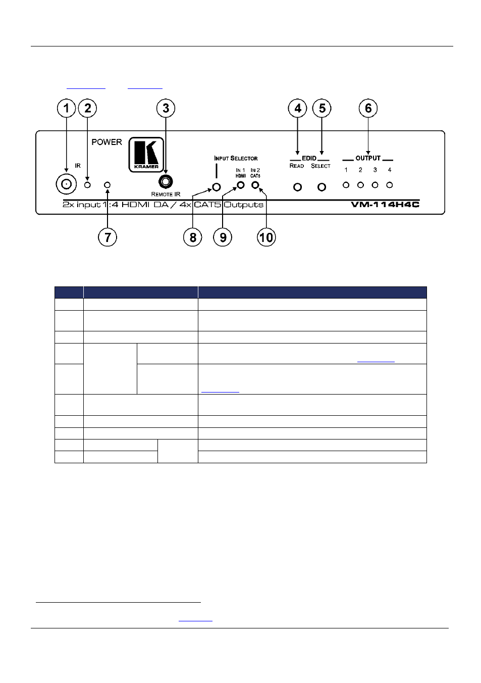
define the front panel the VM-114H4C.
Figure 1: VM-114H4C Front Panel
Table 1: VM-114H4C Front Panel Features
#
Feature
Function
1
IR Remote Control Sensor
Sensor for the remote control IR transmitter
2
IR LED
Lights yellow when receiving signals from the IR remote control
transmitter
3
REMOTE IR 3.5mm Mini Jack
Connect to a remote infrared sensor
4
EDID Buttons
READ Button
Press (when one of the input LEDs is flashing to indicate a
selected input) to read the selected EDID (see
Section 5.2
5
SELECT Button Press repeatedly to cycle through the inputs to select an input from
which to read the EDID. The relevant LED flashes (see
Section 5.2
6
OUTPUT 1~4 LEDS
The relevant LED lights green when an acceptor is connected to
the output
1
7
POWER LED
Lights green when the unit receives power
8
INPUT SELECTOR Button
Press to select an input. The relevant input LED lights
9
IN1 (HDMI) LED
Input
LEDs
Lights green when HDMI input 1 is selected
10
IN2 (CAT5) LED
Lights green when the TP input 2 is selected
1 Also lights or flashes during EDID setup (see