Festo Линейные модули HMP User Manual
Page 43
HMP−...−B−...
Festo HMP−...−B−... 0408NH English
43
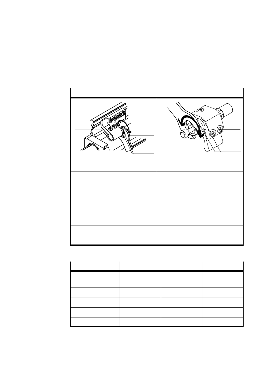
Accurate adjustment of an end position:
On the stop
On the shock absorber
aG
aI
(u)
aE
(v)
bJ
1. Pressurize the compressed air port of the end position to be adjusted.
2. Remove the housing cover
2 of the linear module HMP−...Ă.
3. Loosen the locking screws
aG by
2Ăturns.
4. Turn the stop with a wrench at
aI until
the desired end position is reached.
(Note maximum values (u) in accordĆ
ance with the following table)
5. Tighten the locking screws
aG
(tightening torque see table).
3. Loosen the locking screws
aE by
2Ăturns.
4. Turn the shock absorber sleeve (and the
shock absorber) with a wrench at
bJ
until the desired end position is
reached (Note maximum values (v) in
accordance with the following table).
5. Tighten the locking screws
aE
(tightening torque see table).
6. Repeat the settings for the opposite end position.
7. Fasten the housing cover
2 again.
8. Exhaust the linear module type HMP−... .
Fig. 31
HMP−...
16
20/25
32
Width across flats
aG / aE / aI / bJ
3 / 3 / 13 / 13
4 / 4 / 17 / 17
4 / 4 / 22 / 22
Maximum setting (u)
10 mm
12.5 mm
15 mm
Maximum setting (v)
10 mm
12.5 mm
15 mm
Tightening torque
aG
2.9 Nm
5.9 Nm
5.9 Nm
Tightening torque
aE
2.9 Nm
5.9 Nm
5.9 Nm
Fig. 32