Troubleshooting – Muxlab HDMI over IP Extender with PoE User Manual
Page 2
© MuxLab Inc. 2014
2.
Verify that the distance between the HDMI Encoder and Decoder is within MuxLab
specifications (see Specifications table).
3.
To install the Encoder:
3a. Connect the Encoder to the HDMI video source with an HDMI compliant cable.
3b. Connect one (1) length of Cat 5e/6 (or higher) grade UTP cable to the RJ45 LINK
connector on the Encoder.
4.
To install the Decoder:
4a. Connect the Decoder to the HDMI display equipment with an HDMI compliant cable.
4b. Connect one (1) Cat 5e/6 cable to the RJ45 LINK connector on the Encoder.
5.
If the configuration is a point-to-multipoint or multipoint-to-multipoint:
5a. You will need to use an Ethernet Switch with Gigabit port, DHCP Server and IGMP
Protocol. Verify that the Ethernet Switch is configured correctly and that the
DHCP Server and IGMP Protocol are enabled. See the operating manual for more
information about configuring the Ethernet Switch.
5b. Connect all Encoders and Decoders to the Ethernet Switch.
5c. Use the DIP Switches to select a unique Device ID for each Encoder present on the
network and configure each Decoder Device ID to the corresponding selected Encoder.
Note: This step is not necessary if the management software is used.
6.
Powering the Encoder or Decoder via an external power supply is only necessary where PoE
(PSE) is unavailable. If PoE is unavailable, connect the 5 VDC power supply to the Decoder
first, and then plug the power supply into an AC power outlet. Connect the 5 VDC power
supply to the Encoder first, and then plug the power supply into an AC power outlet. If power
is present, the green power LED of the Encoder and the Decoder will be ON.
Note: Power ‘ON’ the HDMI over IP Extender only after all connections have been
made.
7.
Power ‘ON’ the HDMI equipment and verify the image quality.
8.
This product supports IR pass-thru control. If infrared remote control is needed to control the
Source equipment from the Display, connect the IR Sensor to the 3.5mm Stereo Jack of the
receiver and the IR Emitter to the 3.5mm Mono Jack of the Transmitter.
Note: You can differentiate the IR Sensor and the IR Emitter by looking at the 3.5 mm
plug. The IR Sensor is using a Stereo Plug (3 Contacts) and the IR Emitter a
mono plug (2 Contacts).
9.
Position the IR Sensor so that it is directed at the hand-held remote control. For a clear IR
signal reception, aim the hand-held remote control to the top of the IR Sensor enclosure.
10.
Position the IR Emitter as close as possible to the source’s IR Sensor (i.e. DVD player). For a
clear IR signal reception, the IR Emitter can be glued on the source’s IR Sensor. The IR
Emitter’s signal is transmitted from the side of the enclosure.
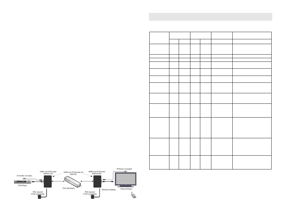
11.
The following diagram illustrates a typical point-to-point LAN configuration.
Troubleshooting
The following table describes some of the symptoms, probable causes and possible solutions in regard to
the installation of the HDMI over IP Extender Kit with PoE:
Symptom
Encoder LEDs Decoder LEDs
Probable
Cause
Possible
Solutions
Power
Link
Power
Link
No Image
OFF
OFF
OFF
OFF
No power
• Check power connections
• Check PoE Ethernet Switch
Setup
No Image
ON
OFF
ON
ON
Internal Error
• Reboot the Encoder unit.
No Image
ON
ON
ON
OFF
Internal Error
• Reboot the Decoder unit.
No Image
ON
ON
ON
ON
UTP Cable
• Check the Encoder UTP
cable.
No Image
ON
BLINK
ON
ON
UTP Cable
• Check the Decoder UTP
cable.
No Image
ON
BLINK
ON
BLINK HDMI Cable
• Check the HDMI Cable
Quality.
Choppy Image
ON
BLINK
ON
BLINK Ethernet Switch • For Multipoint-to-Multipoint
enable the IGMP mode of the
Gigabit Ethernet Switch.
Choppy sound
ON
BLINK
ON
BLINK Synchronization • Check cable length
• Check the HDMI Cable
Quality.
Image flickers
when powering
up nearby
equipment
ON
BLINK
ON
BLINK Interference
• Use STP cables
IR not
functioning
ON
BLINK
ON
BLINK Remote control
not directed to
the IR Sensor or
IR Emitter not
directed to the
source.
• Make sure the IR Sensor is
directed towards the remote
and the IR Emitter to the
equipment
IR not
functioning
ON
BLINK
ON
BLINK Interference
from sunlight,
Fluorescent,
Neon or
Halogen lights
• Place the IR equipment away
for the interfering light
IR not
functioning
ON
BLINK
ON
BLINK Interference
from RF
radiation from
the TV
• Place the IR equipment away
for the RF radiation
If you still cannot diagnose the problem, please call MuxLab Customer Technical Support at 877-689-
5228 (toll-free in North America) or (+1) 514-905-0588 (International).