Troubleshooting, Application tips – Muxlab Shielded CATV Balun User Manual
Page 2
© MuxLab Inc.
8.
Connect one Shielded CATV Balun to the RF output at the head-end.
9.
Caution: Do not mount the balun over equipment ventilation openings. Covering the
openings may cause the equipment to overheat.
10. Connect a line cord from the RJ45 modular jack of the Shielded CATV Balun to the hori-
zontal wiring of the building.
11. At the receiver end, connect a Shielded CATV Balun to the set-top tuner or cable modem.
12. Connect a line cord from the RJ45 connector of the Shielded CATV Balun to the appro-
priate modular video wall outlet.
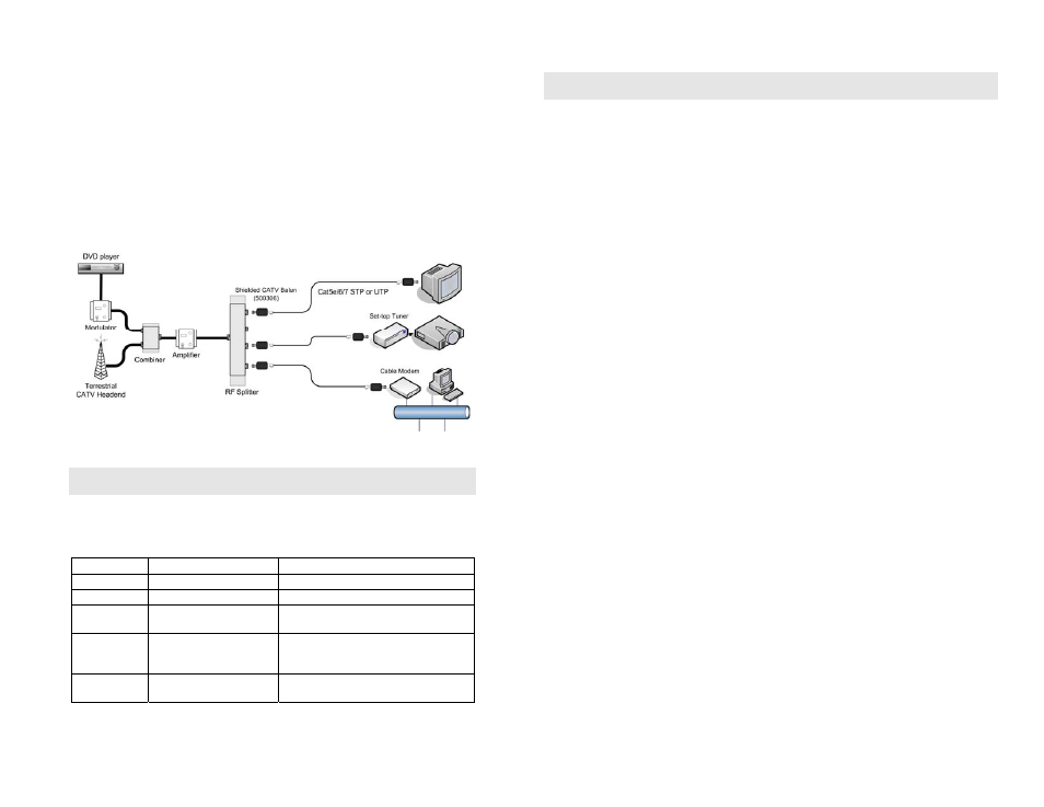
13. Power on the video equipment. See typical application below.
Troubleshooting
The following table describes some of the symptoms, probable causes and possible solutions in
respect to the installation of the Shielded CATV Balun. If you still cannot diagnose the prob-
lem, please call MuxLab Customer Technical Support at 877-689-5228 (toll-free in North
America) or (+1) 514-905-0588 (International).
Symptom
Probable Causes
Possible Solutions
No video
No continuity in video link
Check cable continuity between baluns.
No video
No power
Check power supplies.
No video
Improper connection
Swapped pairs
Check that baluns are connected to correct
video inputs and outputs.
Snowy picture
Insufficient signal strength
Increase signal power at head-end using a
“tilt” amplifier. Verify cable grade. Use
higher grade cable if necessary.
Over bright
image
Signal strength too high
Attenuate signal by reducing amplifier gain
or by inserting a signal attenuator in the link.
Application Tips
In a point-to-point scenario for CATV (superband and hyperband), VHF and FM, cable lengths of up to 45
meters may be achieved without amplification if the nominal input is about 15dBm. In some applications,
a tilt amplifier may be required since the STP losses are higher than coax at the higher frequencies. Linear
gain compensation of up to 20-25dB at 750MHz is usually adequate. Conversely, if amplification is used
to compensate for losses at higher frequencies and long distances, it may be necessary to attenuate the
lower frequency, shorter distance signals to avoid over-driving the TV monitors. The Shielded CATV
Balun may be used in conjunction with tilt/gain amplifiers, CATV splitters and splitters with built-in am-
plifiers. The following are some helpful guidelines when planning your cabling:
1.
Try for 10dBmv of signal level at each television channel. Use a little more for big screen TVs.
Measure the signal level at the high and low end of the spectrum to determine whether a tilt amplifier
is needed.
2.
When laying out your system, there will be approximately 5dB of signal loss per 100' of RG6-
coaxial cable.
3.
Please ensure all splitters and amplifiers are broadband. For UTP installations, splitters should have
5 MHz to 900 MHz bandwidth with a bi-directional filter at 5 to 50 MHz.
4.
Check and make sure that all televisions are set up for the proper frequency spectrum (i.e. UHF or
cable).
5.
If extra channels are available, allow 1 to 2 channels spacing between “modulated” and "active"
channels.
6.
Always compensate for insertion loss with a good amplifier. There will always be a drop in signal
strength when combining a modulator to an existing system due to insertion loss from the combiner.
7.
When combining an existing signal with a modulated signal, make sure to have equal signal strength
at the point of the combiner so one signal does not degrade the other.
8.
When possible, use the lowest frequencies available for the modulated channels. Lower frequency
channels have lower signal loss on the cable runs.
9.
When in doubt, run the signal a little high to the television and use an attenuator to lower the signal
strength going into the TV. Attenuators may be combined (i.e. two -3dB attenuators will = -6dB).
10. Combine the modulator into the video distribution system as far "up-stream" as possible.
11. If the system needs to be amplified, use the amplifier as far "up-stream" as possible. For example,
place one amplifier at the head end and one tilt amplifier in each wiring closet where the baluns are
located.