Troubleshooting, Specifications, Environment – Muxlab CCTV Pass-Thru Balun User Manual
Page 2: Video, Bandwidth
© MuxLab Inc.
4. Connect the Blue/White-Blue wires to the control input of the camera. Please
ensure straight-through polarity between the CCTV camera and the remote
control device.
Remote Low Voltage Power (optional):
5. If remote low voltage power is being sent to the camera, first ensure that the
power supply is off before making any connections.
6. Connect the red and black wires to the power input of the camera. Please
ensure straight-through polarity between the CCTV camera and the remote
control device. Remote power is transmitted via two twisted pairs up to the
camera. MuxLab provides a guideline for maximum distance based on camera
power requirement as stated in the specification section. Please consult the
CCTV equipment manufacturer for more detailed performance specifications.
7. Complete the connection between the two baluns, using straight-through 4-pair
unshielded twisted pair cable and cross-connect blocks as required. The
CCTV Balun is reverse polarity sensitive. Please ensure that straight-through
wiring is maintained.
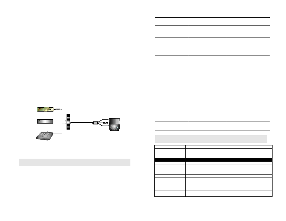
8. At the remote end, the video, power and control signals are ungrouped
following the specified pair assignment and respecting the signal polarity. The
following diagram shows a typical configuration.
Power (24VAC)
DVR
Control (RS-422, RS232)
500009
Control
Power
Video
4-pair Cat5 cable
RJ45
500022
Camera
RJ45 to 110 block
9.
Power-on the CCTV equipment and check the picture quality. The video
should be clear and sharp within the maximum specified distances.
Troubleshooting
The following table describes some of the symptoms, probable causes and
possible solutions regarding the CCTV Pass-Thru Balun. If you still cannot
diagnose the problem, please call MuxLab Technical Support at 514-905-0588.
Symptom
Probable Causes
Possible Solutions
Poor picture quality,
distortion, interference
1. EMI interference.
Check that wiring is not too close
to transformers and ballasts.
2. Wires reversed on signal
pair on one side
Make sure that the wires on the
signal pair are not reversed on
one side.
3. Split pair
Check if the UTP pairs are split
and correct. Each signal pair
must be twisted.
Symptom (cont’d)
Probable Causes
Possible Solutions
No video image
1. Power-off.
Check power supplies of CCTV
equipment.
2. Wrong pin configuration Check pin configuration and
verify straight-through wiring.
3. Defective CCTV Balun
Change CCTV baluns for another
pair.
Picture faded or weak
1. Exceeded distance
specifications
Check DC loop resistance and
verify if distance spec is
exceeded. Reduce cable length or
eliminate high-loss components.
2. Lower grade UTP cable is
introducing high signal
losses.
Use signal repeater for extended
distance or replace cable by
higher grade.
No power at camera
1. Wrong pin config.
Check wiring
2. Distance exceeded
Move power closer to camera.
PTZ controls not
responding
1. Wrong pin config
Check wiring.
Specifications
Environment
Baseband video: NTSC, PAL, and SECAM.
Devices
Close circuit TV (CCTV) cameras, monitors, switchers, sequencers, multiplexers,
digital video recorders (DVR) and other CCTV equipment.
Transmission
Transparent to the user.
Video
Bandwidth
DC to 8 MHz.
Impedance
Input: 75 ohms (BNC); Output: 100 ohms (RJ45)
Maximum Input
1.1Vp-p
Insertion Loss
Less than 2 dB per pair over the frequency range from DC to 8 MHz
Return Loss
Greater than 15 dB over the frequency range from DC to 8 MHz
Common Mode
Rejection
Greater than 40 dB @ 8 MHz
Max. Distance – Color
Cat 3 –1,200 ft (365m); Cat 5 – 2,200 ft. (670m)*
*Certain models of DVR may yield shorter distances of 1,000 to 1,500 ft
Max. Distance – Black
& White
Cat 3 –1,500 ft (457m); Cat 5 – 2,500 ft (762m)