Connection specifications – RMS Technologies IMDE23 INTEGRATED MOTOR+DRIVER+ENCODER User Manual
Page 7
RMS Technologies
Page 7
Version 1.17
R164 Controller Manual
09/15/2005
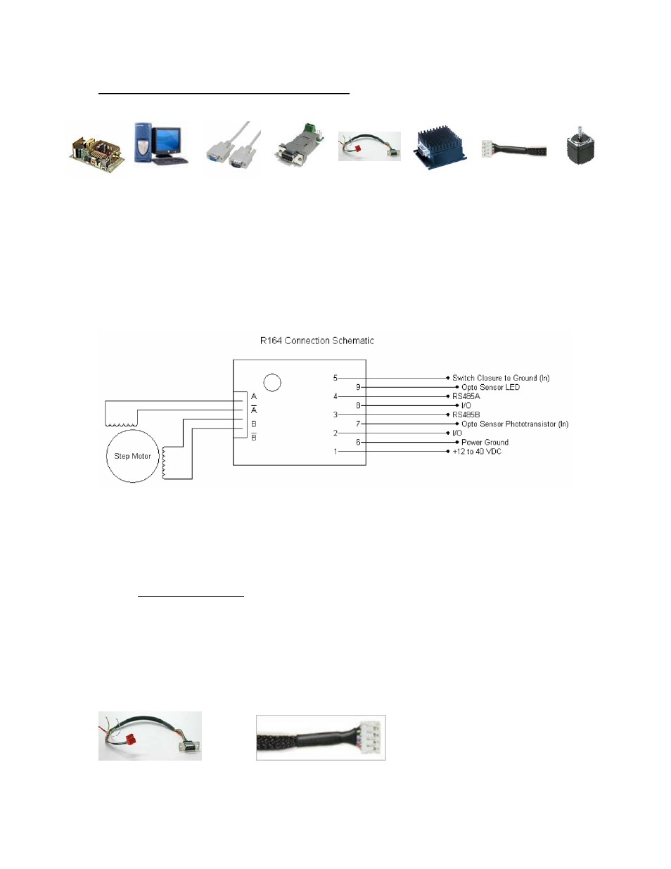
6. CONNECTION SPECIFICATIONS
Quick Start
1
2
3
4
5
6
7
8
Figure 3: List of Parts
List of Parts:
1. Suitable DC Power Supply (+12 to 40 VDC)
2. PC with a Serial COM Port
3. DB9 Male-to-Female Serial Port Cable (Not Included)
4. RS485-to-RS232 Converter Card
5. 90-022 Cable to connect the Controller to Power and Controls
6. R164 Controller
7. 90-018 Cable to connect the motor to the R164
8. Appropriate Step Motor
• Connect the Female end of the DB-9 Serial Cable
(3)
to your PC
(2)
and connect the Male
end to the RS485-to-RS232 Converter Card
(4)
• Take the 90-022 cable
(5)
and connect the Red 4-Pin connector to the Converter Card
(4)
• Then take the other end of the 90-022 DB-9 cable
(5)
and connect it to your R164
Controller
(6)
.
• Twist together the lead wires of the motor
(8)
with the lead wires end of the 90-018
cable
(7).
Red = A, Blue = A-, Green = B, Black = B-. See Wiring Diagrams at
www.rmsmotion.com
• Next, connect the 4-Pin Connector end of 90-022 cable
(7)
with the R164 Controller
(6)
• Finally, connect your Power Supply
(1)
to the Green +/- pins on the Converter Card
(4)
• Now you are ready to use your R164 Controller, on your PC
(2)
, open up HyperTerminal
from Programs Æ Accessories Æ Communications
Mating Connectors
A mating D-Sub connector and crimp style connector are provided.
Part # 90-022
Part # 90-018