RMS Technologies IMDE23 INTEGRATED MOTOR+DRIVER+ENCODER User Manual
Page 6
RMS Technologies
Page 6
Version 1.17
R164 Controller Manual
09/15/2005
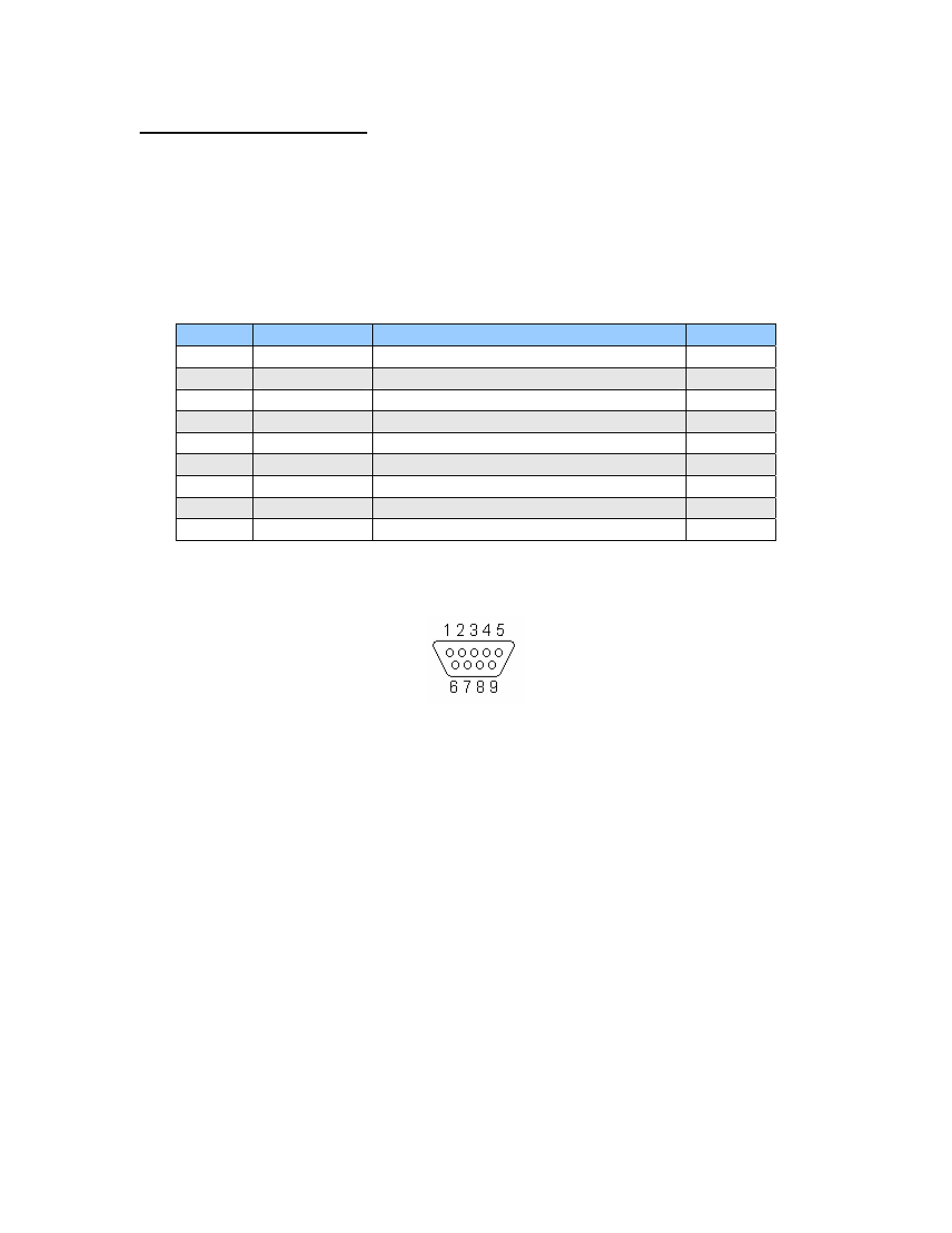
5. PIN ASSIGNMENTS
A DB-9 female connector cable receives power and provides the control connections
for the R164 Controller. On the opposite end of the DB-9 female connector cable,
there is a 4 pin connector provided for the converter card in order for the controller
to communicate with the PC. This allows the user to solder and program the switch
push button and the Opto Sensor, enabling several options. The two I/O wires are
colored blue and black. This will allow for options such as solenoids, relays, opto
isolators, LED’s and many other input and output connections. See Table 2 below for
details.
Pin #
Color
Function
Input*
1
Red
+V (Main Power In)
2
Black
I/O
1
3 Brown
RS485B
(-)
4
Black/White RS485A (+)
5
Orange
Switch Closure to GND (IN)
4
6
Green
GND (-V of main power in)
7
White
Opto Sensor Phototransistor (IN)
3
8
Blue
I/O
2
9
Yellow
Opto Sensor LED (Power Out)
Table 2: Pin Assignments
*Inputs are labeled 1, 2, 3 and 4 for programming the ‘Halt’ and ‘Skip’ Commands.
Figure 2: DB-9 Female Cable Connector (Rear View)