RMS Technologies IMDE23 INTEGRATED MOTOR+DRIVER+ENCODER User Manual
Page 11
RMS Technologies
Page 11
Version 1.17
R164 Controller Manual
09/15/2005
Connecting the Accessory Pieces
If you have purchased the Designer’s Kit, there is a Red Push Button and an Optical
Sensor included. Follow the schematics below in order to properly assemble
accessory pieces.
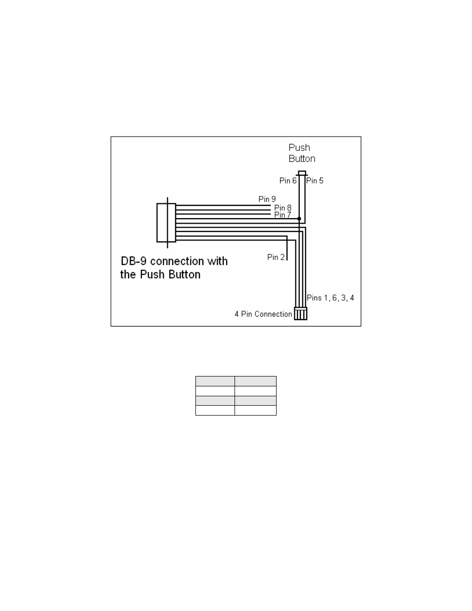
Push Button
Figure 6: Push Button Schematic
It is best to solder the Push Button to Pin 5 which corresponds to Input 4, then
solder Pin 6 (Power Ground) to the other side of the push button.
Input 1 Pin 2
Input 2 Pin 8
Input 3 Pin 7
Input 4 Pin 5
Table 4