RMS Technologies IMDE23 INTEGRATED MOTOR+DRIVER+ENCODER User Manual
Page 14
RMS Technologies
Page 14
Version 1.17
R164 Controller Manual
09/15/2005
8. MOTOR CONNECTIONS
Step Motors have 4, 6, or 8 wires. To better understand how to connect your step
motor with your R164 Controller, follow the Figures below for the corresponding
motor. NOTE: The dots indicate the starting position of the wires when wound.
4 Lead Wire Motor Connection
Connect one set of windings to the A terminals. Connect the other set of windings to
the B terminals. If the set of windings is unclear, take a pair of wires; use an
ohmmeter to check for continuity. When you find the first two wires that have
continuity, connect it to the A terminals. Connect the other two to the B terminals.
Figure 9.1: 4 Lead Wire Motor Connection
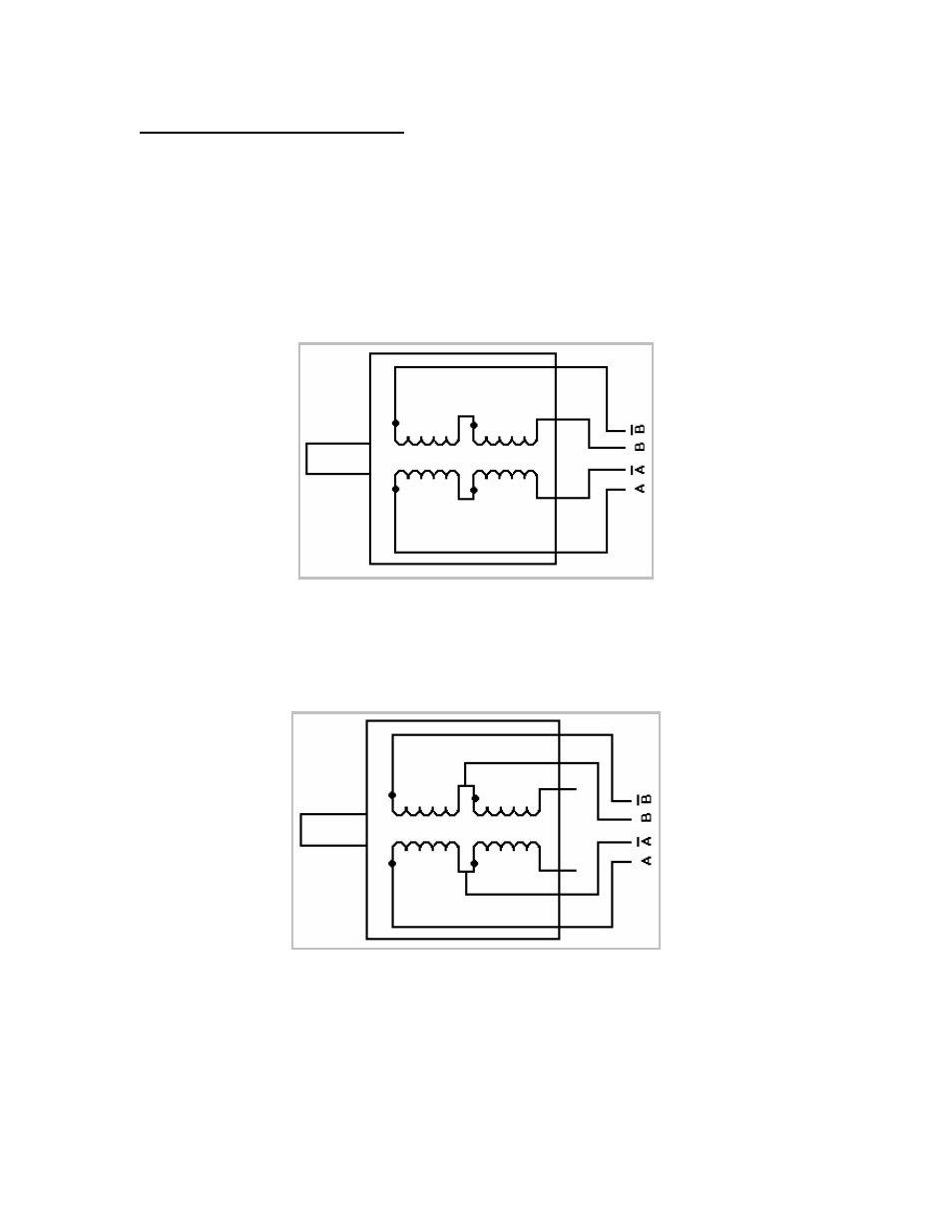
6 Lead Wire Motor Connection (Half Winding)
Six wire motors can be wound in two ways: Half Winding and Full Winding. Six wire
motors contain a center tap on each of the two windings. For a half-winding
connection, the center tap and one end of the wires are used.
Figure 9.2: 6 Lead Wire Half Winding Connection