RMS Technologies IMDE23 INTEGRATED MOTOR+DRIVER+ENCODER User Manual
Page 12
RMS Technologies
Page 12
Version 1.17
R164 Controller Manual
09/15/2005
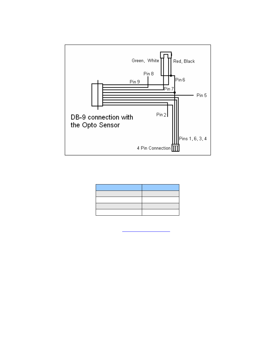
Optical Sensor
Figure 7: Opto Sensor Connection Schematic
The Opto Sensor uses Pins 6, 7, and 9. Use the following table to solder the
corresponding wires.
Optical Sensor
DB9 Cable
Green Æ
Green
Black Æ Green
Red Æ
Yellow
White Æ White
Table 5
For a list of commands, please visit
www.rmsmotion.com
Æ Downloads Æ R164
Commands.