Install the rotating element, Confirm the seal chamber runout – Goulds Pumps 3640 - IOM User Manual
Page 77
Maintenance
API limits are listed in the Shaft and rotor runout requirements table.
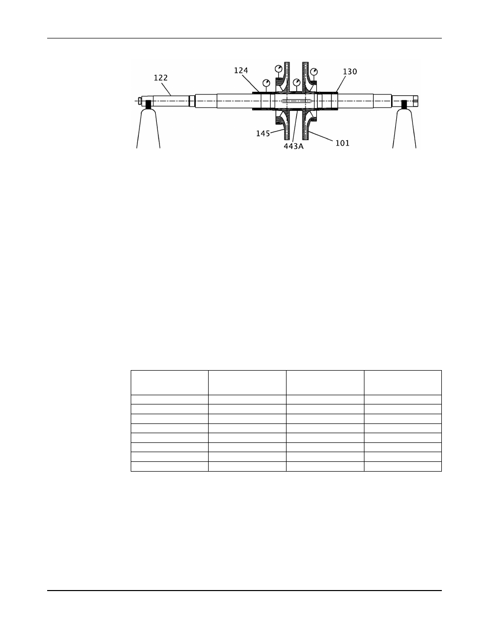
Install the rotating element
Confirm the seal chamber runout
The bearing housings are doweled to the
head (184) and
casing (100) during the original build. However, in order to assure the correct running position
of the shaft, use this procedure in order to confirm the seal chamber runout before you install
the cartridge mechanical seals:
1. Install the old bearings on the shaft and bolt the bearing housings to the casing and head.
2. Mount the dial indicator on the shaft (122). Rotate the shaft (122) so that the indicator rides
along the seal chamber bore for 360°.
3. If the total indicator reading exceeds 0.005 in. (0.127 mm), determine the cause and make
corrections.
It may be necessary to readjust the housing.
a) Remove the dowel pins and use the adjusting screws to bring the runout to within 0.002
in. (0.0508 mm).
b) Redowel the housings in a different location.
4. Check the seal-chamber face runout.
a) With a dial indicator mounted on the shaft, rotate the shaft so that the indicator rides
along the seal-chamber face for 360°.
b) If the total indicator reading exceeds the allowable runout as this table shows,
determine the cause and make corrections.
Frame group
Nameplate radial
Seal chamber bore
Maximum allowable
bearing
total indicator reading
in (mm)
in (mm)
S
6407
3.5433 (90)
0.0018 (0.045)
M
6309
4.7244 (120)
0.0024 (0.060
L
6312
5.1181 (130)
0.0026 (0.065)
XL1
6312
5.5118 (140)
0.0028 (0.070)
XL2
6217
6.6929 (170)
0.0033 (0.085)
XL3
6317
6.6929 (170)
0.0033 (0.085)
XL5
6320
7.8740 (200)
0.0039 (0.100)
XL5
6224
7.8740 (200)
0.0039 (0.100)
5. Remove the dowel pins and unbolt the bearing housings. Discard the old bearings.
Model 3640 Installation, Operation, and Maintenance Manual
75