Appliance diagram – Magikitch'n MKO60 User Manual
Page 9
9
4. APPLIANCE DIAGRAM
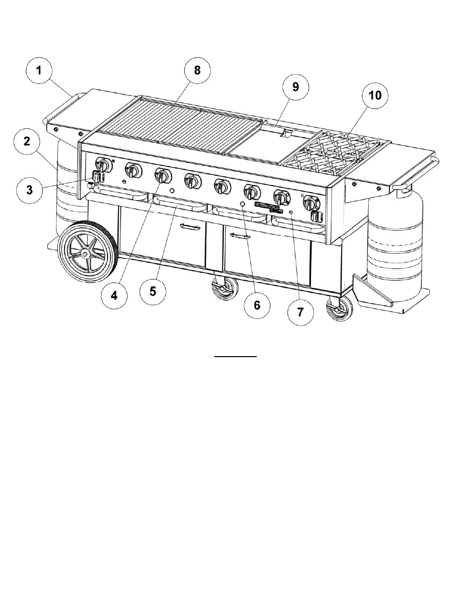
FIGURE 4
4.1. Operational Features
The diagram above outlines some of the key operational components of your appliance, see Figure 4.
1. Side Service Shelf
Side service shelves are fixed in place, and are standard equipment on models equipped with a mobile base.
2. Self Contained Propane Cylinder
Propane cylinders used with this appliance must be constructed and marked in accordance with the specifications for
propane cylinders of the US department of Transportation (DOT), and for specifications for LP-gas cylinders of the
National Standard of Canada, CAN/CSA-B339, cylinders, spheres, and tubes for the Transportation of Dangerous
Goods.
3. Pilot Knob, I/O (On/Off)
In the “On” position this knob will allow gas to flow to the pilot runner tubes, and the gas supply for the main burners.
Models 45 and 60 may have two (2) pilot knobs, 1 on the left and right side of the appliance.
4. Main Burner Valve, Off/On/Low
Allows gas to flow to the main burners. This should only be in the on position if the pilot runner tubes have been
ignited and flame has been verified. These knobs may also be used for the side burner valve(s) (12), see figure 5, if so
equipped.