Installation instructions – Magikitch'n MKO60 User Manual
Page 8
8
C. Ensure that ¼-20 wing nuts (E) are loosened enough to allow the cylinder bracket(s) (D) to move up and down freely.
D. Place the bottom ring of the propane cylinder(s) (9) into the receiving hole of the base bottle support bracket(s) (C).
While holding the cylinder securely, insert the top ring of the cylinder (9) into the slots of the bottle retaining bracket
(D). Tighten the ¼-20 UNC wingnut(s) (E) so the bottle cylinder retaining bracket(s) are secured.
E. Connect the gas regulator assembly(s) (7) to the hose connection located at the top of the cylinder (9). The
green QCC1 connector on the hose assembly screws onto the threaded connection hand-tight.
3. INSTALLATION INSTRUCTIONS
Note:
This appliance is intended to operate with an approved self contained propane cylinder with a minimum
capacity of 40 Lbs.
Units may be installed with 0
” minimum clearance from sides and back to non-combustible construction in areas that are non-
combustible locations. This unit is not approved for installation in combustible constructions.
Important- Ensure that the gas regulator hose assembly has been properly installed prior to continuing. For built in, or fixed gas
supply appliances ensure that the provided gas regulator has been installed.
If required by local codes, the vent line from the gas appliance pressure regulator shall be installed to the outdoors in accordance therewith.
In the absence of local codes, the vent line shall be installed in accordance with the National Fuel Gas Code, ANSI
Z223.1/NFPA54, Natural Gas Installation Code, CAN/CGA-B149.1, or the Propane Installation Code, CAN/CGA-149.2,
as applicable.
3.1. Gas Information
The energy requirements for your appliance can be found on the data information plate located on the inner sidewall.
Orifices are sized to provide proper gas flow to the rated BTU/hr for each model. Regulator pressure must be measured
and adjusted before the unit goes into service, following installation and when operational performance is in question. The
manifold and supply pressure readings are taken at the pressure test points provided.
3.2. Leak Testing
When the gas connections and installation is complete, it must be tested for gas leaks before use. Turn all burner control
valve(s) to the
“off” position. Wet all gas line fittings and connectors with a solution of soapy water (or commercial leak
disclosing liquid). Follow the lighting instructions in Section 6 to light the runner tubes only and look for bubbles or foam at any of
the joints in the system. If a leak is found, close the main gas valve immediately and call your local dealer, the ASAP agency
or .the manufacturer.
If the gas connections are leak-free, the unit is ready to use. Continue to follow the lighting instructions in Section 5.
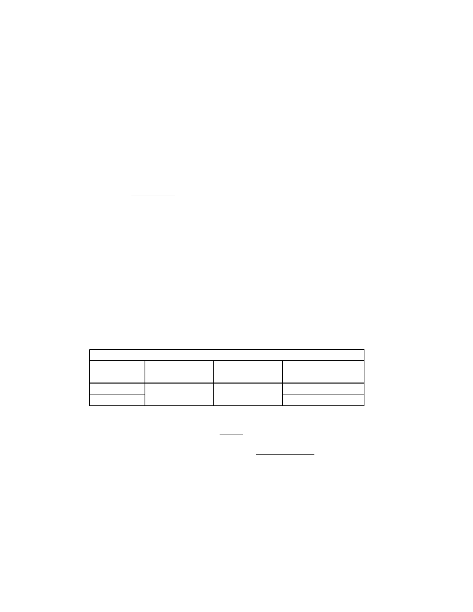
Gas Type
BTU/Hr (kW)
per Main Burner
BTU/Hr (kW)
per Side Burner
Manifold Pressure
All Models
Natural
4.0" WC (10.1 cm)
Propane
10.0" WC (25.4 cm)
20,000 (5.86)
25,000 (7.33)
GAS INFORMATION