Installation of led lightbars, Operation of ulx210, Required tools – Varad ULX210 - Color Changing LED Under Car Lighting System User Manual
Page 6
Visually inspect underneath your vehicle to determine a suitable
location for mounting each LED lightbar. Hold the LED lightbar up
in the prospective mounting location to verify that it will not
interfere with existing parts under the vehicle. When you have
found a suitable location, begin to install the mounting clamps.
There are 4 clamps for each side lightbar and 2 for each front and
rear lightbar. Space each clamp approximately 1 foot between
each other. It is important to install all mounting clamps in a
straight line. It helps to use a reference point on the chassis such
as the pinch weld seam, etc. Mark each drilling point and pre-drill
each hole with a 1/8” drill bit. Install all clamps facing the same
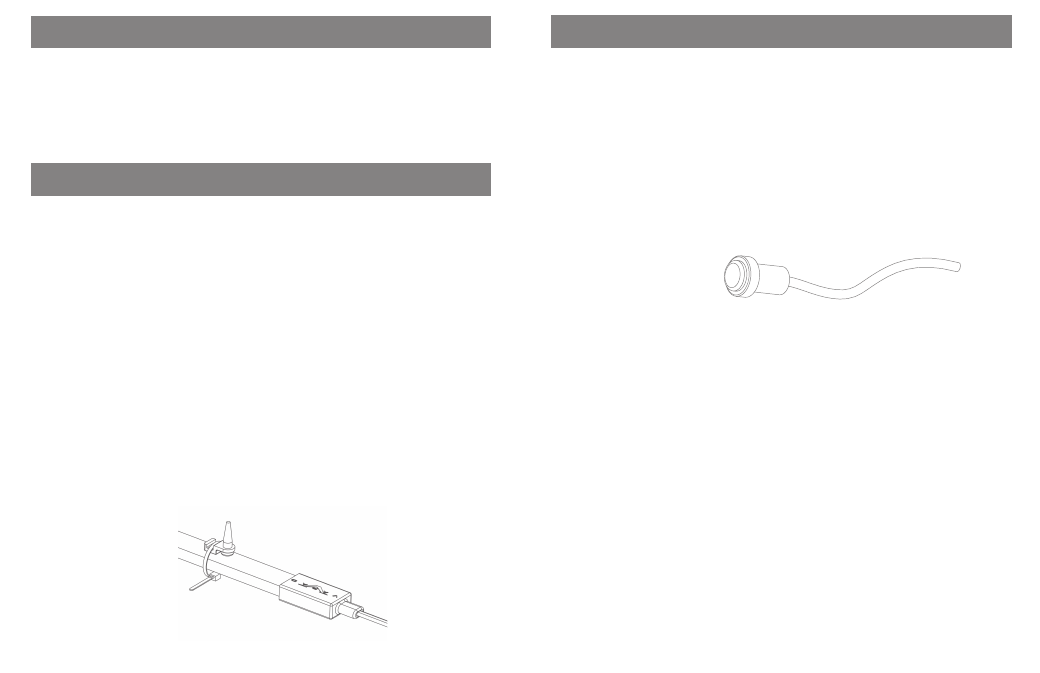
direction. Now hold the lightbar up and install a tie strap through
the clamp at each mounting point. Trim excess tie strap material.
Repeat the process for each lightbar. At this point take the wires
from each end of the light bar and run them towards each other
once again location to verify that it will not interfere with existing
parts under the vehicle. Cutting away excess before attaching like
colored wires and heat shrinking.
Installation of LED lightbars
• Wire stripper
• Wire cutter
• Assorted drill bits
• Cordless drill
• Screwdriver
Screw clamp to body
and then tie strap
around light bar
Operation of ULX210
The ULX210 is operated with a single button remote control. All
features can be controlled by two types of button operations:
• “Push and Hold” (greater than 1 second) to change modes.
• “Push and release” (momentary) to change features in
selected mode.
For example:
To turn system “ON”
Push and hold button until Mode 1 is active. The system will power
up and go into Mode 1 (Color Wash). The default color is blue. Push
button momentarily and system will begin the color wash. Each
momentary push of the button will stop or start the cycling. Refer
to “Mode Operation Flow Chart” for more details.
3
8
Required tools
Push button switch