Drive parameters – Beijer Electronics AN-BEI-P2-038 User Manual
Page 7
APPLICATION NOTE AN‐BEI‐P2‐038
Date: 15/02/12
AN‐BEI‐P2‐038 Modbus RTU Control and Register Mapping
7
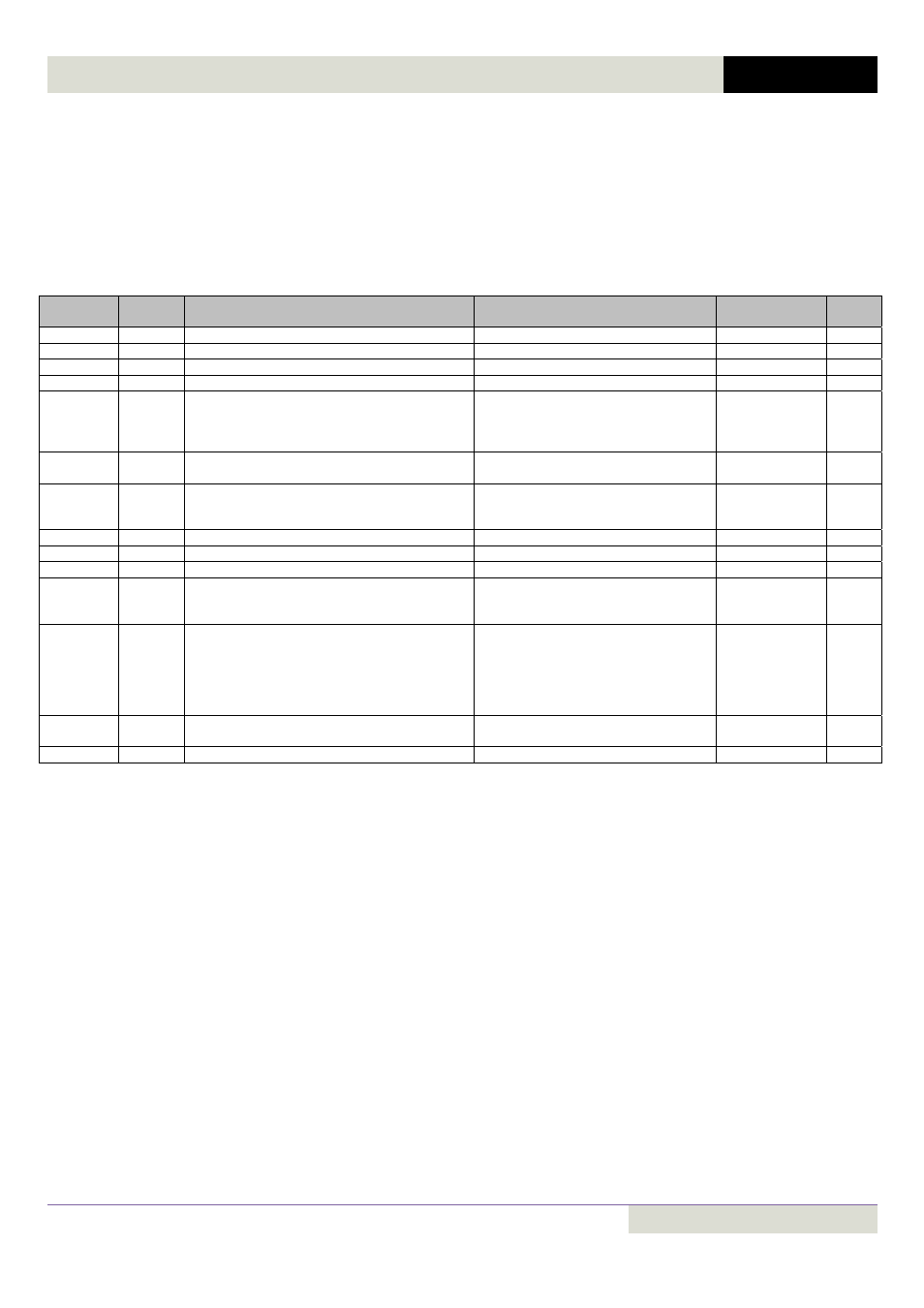
Drive Parameters:
All User Adjustable parameters in Groups 1 to 8 can be accessed by Modbus. For further details regarding the parameter
functions, please refer to the Beijer Frequency Inverter P2 User Guide.
Register Type definitions are defined as follows
WORD Hexadecimal Word
U16
Unsigned 16 Bit Value
S16
Signed 16 Bit Value
Group 1 : Basic Parameter Set (Level 1)
Parameter
Number
Register
Number
Description
Range
Scaling
Type
P1‐01
101
Max Frequency Limit
0 to 30000
3000 = 50.0Hz
U16
P1‐02
102
Min Frequency Limit
0 to 30000 (Limited by P1‐01 Setting)
3000 = 50.0Hz
U16
P1‐03
103
Acceleration Ramp Time
0 to 6000
300 = 30.0s
U16
P1‐04
104
Deceleration Ramp Time
0 to 6000
300 = 30.0s
U16
P1‐05
105
Stop mode
0: Ramp to Stop
1: Coast to Stop
2 = Ramp to Stop, Brake Transistor Enabled
3 = Coast to Stop, Brake Transistor Enabled
U16
P1‐06
106
Energy optimiser
0: Disable
1: Enable
WORD
P1‐07
107
Motor rated voltage
0V, 20V to 250V
0V, 20V to 500V
0V, 20V to 600V
230 = 23 V
U16
P1‐08
108
Motor rated current
20% to 100% of drive rated current
1 = 0.1A
U16
P1‐09
109
Motor rated frequency
25 to 500Hz
50 = 50Hz
U16
P1‐10
110
Motor rated speed
0 to 30 000rpm
1500 = 1500rpm
U16
P1‐11
111
V/F Voltage Boost
Auto, 0.1 to 20%
‐1 = Auto
0 = Disabled
1 = 0.1%
S16
P1‐12
112
Control mode
0: Terminal mode
1: Keypad mode (Unipolar)
2: Keypad mode (Bipolar + direction toggle)
3: User PID mode
4: Fieldbus (Modbus, Profibus etc.)
5: Slave mode
U16
P1‐13
113
Digital inputs function select
0: User defined
1...20 see table
U16
P1‐14
114
Extended Menu Access code
0 to 30 000
U16