Control and status register descriptions – Beijer Electronics AN-BEI-P2-038 User Manual
Page 4
APPLICATION NOTE AN‐BEI‐P2‐038
Date: 15/02/12
AN‐BEI‐P2‐038 Modbus RTU Control and Register Mapping
4
63
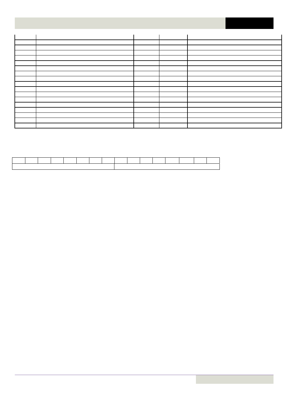
User register 13
03, 06
Read/Write
64
User register 14
03, 06
Read/Write
65
User register 15
03, 06
Read/Write
66
Analog output 1 user
03, 06
Read/Write
67
Analog output 2 user
03, 06
Read/Write
68
Reserved
03, 06
Read/Write
69
Reserved
03, 06
Read/Write
70
Relay output 1 user
03, 06
Read/Write
71
Relay output 2 user
03, 06
Read/Write
72
Relay output 3 user
03, 06
Read/Write
73
Relay output 4 user
03, 06
Read/Write
74
Relay output 5 user
03, 06
Read/Write
75
User display scaling
03, 06
Read/Write
76
User display decimal
03, 06
Read/Write
77
User speed reference
03, 06
Read/Write
78
User torque reference
03, 06
Read/Write
79
User ramp
03, 06
Read/Write
80
Scope index 1, 2
03, 06
Read/Write
Control and Status Register Descriptions:
Read and write registers
Register 1: Drive Control Command Word
15
14
13
12
11
10
9
8
7
6
5
4
3
2
1
0
High byte
Low byte
Bit 0:
Run/Stop command: Set to 1 to enable (run) the drive. Set to 0 to disable (stop) the drive.
Bit 1:
Fast stop request. When set to 1 the drive will decelerate to stop using the 2
nd
deceleration ramp (P2‐25).
Bit 2:
Reset Fault Request. Set to 1 in order to reset the drive following a trip / fault.
(Note : This bit must be reset to zero once the fault is cleared to prevent un‐expected reset)
Bit 3:
Coast stop request. Set to 1 to issue a coast stop command.
For normal operation, Bit 3 has the highest priority, bit 0 has the lowest priority (bit 3>bit 1>bit 0). For example if the control
word is set to 0x0009 by the network master, the drive will do a coast stop rather than run. For normal Start / Stop operation,
bit 0 should be used.
Register 2: Modbus Speed Reference Set‐point
This register is used to send the speed reference value. The input data is a 16bit signed integer including one decimal place. For
example, a value of 500 represents a speed reference of 50.0Hz, 123 represents 12.3Hz. It is also possible to reverse the drive by
sending a negative value in this register. For example, ‐1(0xFFFF) gives ‐0.1Hz. ‐234(0xFF16) gives ‐23.4Hz.
The input value range is from ‐5000 +5000; however the actual drive output frequency will be limited by the minimum and
maximum frequencies set in P1‐02 and P1‐01 respectively.
Register 3 : Modbus Torque Reference Set‐point
This register is used to send the torque reference / limit value when a Modbus torque reference or maximum torque limit is
selected using P4‐06. The value must always be positive with a range of 0 – 2000 = 0.0 – 200.0% of the motor nominal torque
capacity.
Register 4: Modbus Ramp Control Time
This register specifies the drive acceleration and deceleration ramp time simultaneously. This value will override the values set in
parameters P1‐03 and P1‐04 respectively, providing P5‐08 = 1. The input data range is from 0 to 60000 (0.00s to 600.00s)
Read only registers
Register 6: Drive status and error code
High byte : Shows the last drive error / fault code. (Valid when the drive is tripped, a list of error codes is shown later in this
document)
Low byte : Shows the drive operating status (0: drive stopped, 1: drive running, 2: drive tipped)