Modbus telegram structure, Rj45 data connection pin configuration, Typical modbus configuration – Beijer Electronics AN-BEI-P2-038 User Manual
Page 2
APPLICATION NOTE AN‐BEI‐P2‐038
Date: 15/02/12
AN‐BEI‐P2‐038 Modbus RTU Control and Register Mapping
2
Modbus Telegram Structure:
The following Modbus Commands are supported
• 03 Read Holding Registers
• 06 Write Single Holding Register
The telegram structure is as follows:‐
Command 03 – Read Holding Registers
Command 06 – Write Single Holding Register
Master Telegram
Length
Slave Response
Length
Master Telegram
Length
Slave Response
Length
Slave Address
1
Byte
Slave Address
1
Byte
Slave Address
1
Byte
Slave Address
1
Byte
Function Code (03)
1
Byte
Function Code (03)
1
Byte
Function Code (06)
1
Byte
Function Code (06)
1
Byte
1st Register Address
2
Bytes
Byte Count
1
Byte
Register Address
2
Bytes
Register Address
2
Bytes
No. Of Registers
2
Bytes
1st Register Value
2
Bytes
Value
2
Bytes
Register Value
2
Bytes
CRC Checksum
2
Bytes
2nd Register Value
2
Bytes
CRC Checksum
2
Bytes
CRC Checksum
2
Bytes
Etc...
CRC Checksum
2
Bytes
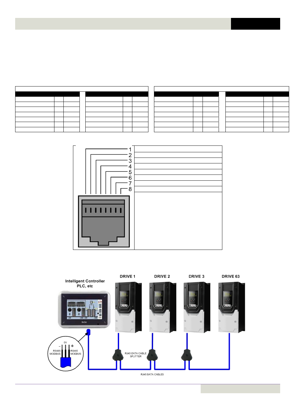
RJ45 Data Connection Pin Configuration:
CAN‐
CAN+
0 Volt
Int bus / Remote Keypad / PC Connection ‐
Int bus / Remote Keypad / PC Connection +
+24 Volt Remote Keypad Power Supply
RS 485‐ Modbus RTU
RS 485+ Modbus RTU
Typical MODBUS configuration: