American Standard Selectronic 195 User Manual
Page 6
M 9 6 5 2 74
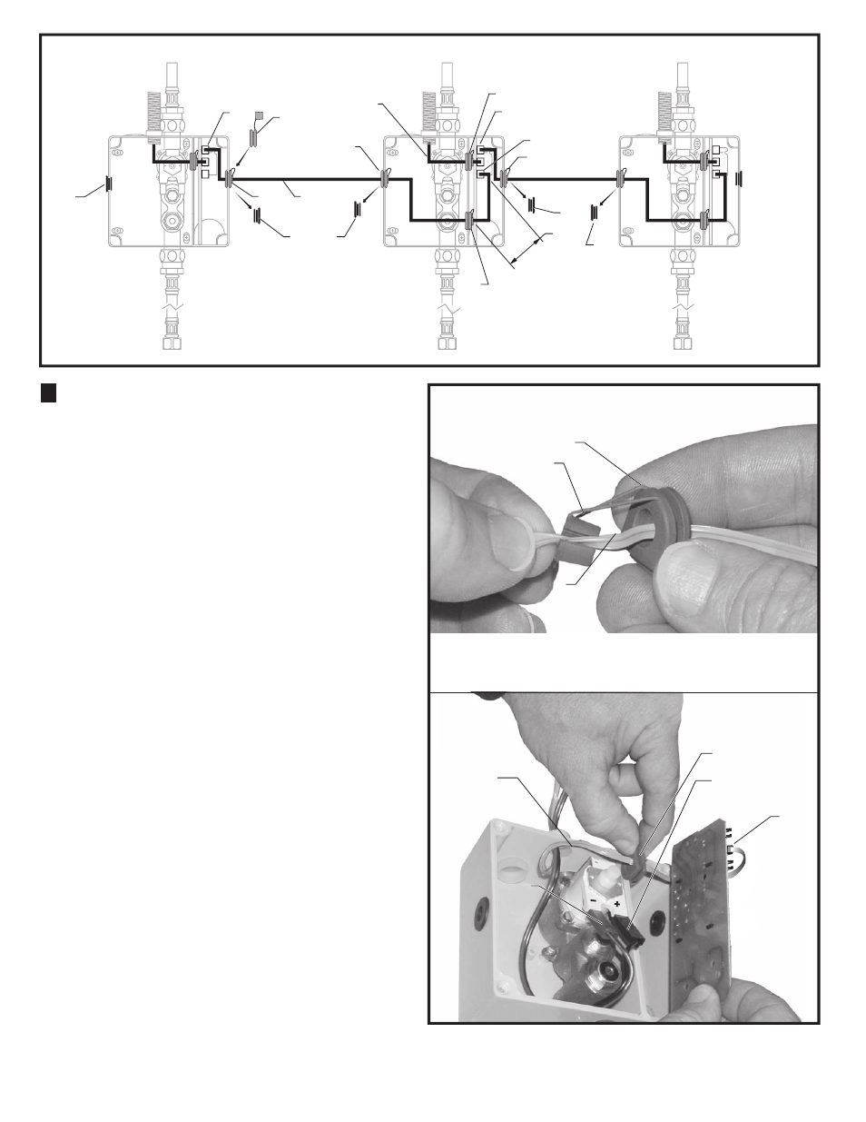
FOR AC-VERSION
(MULTI HOOK-UP); Fig. 2, 3
Unit #1
Unit #2
Unit #3
1. See AC Version Electrical Hook-up for first unit of the
Multi hook-up.
2. Remove ENCLOSURE COVERS from all
ENCLOSURES.
3. Remove SOLID BLACK INSERT(1) from right side
of ENCLOSURE #1 and replace with gray 2-PIECE
GROMMET
(3). Replace solid black inserts on Unit #2
with gray 2-PIECE GROMMET
(3).
4. Take the 10 ft. EXTENSION (2) from Unit #2 and
install into right side of Unit #1 and Left side of Unit #2
insealing wire into SPLIT PLUG
(7) as shown in Fig. 3a.
Push SPLIT PLUG
(7) into GROMMET (8).
5. Insert CONNECTOR from 10 ft. EXTENSION (2) into
CIRCUIT BOARD RECEPTOR
(4) top of Unit #1 as
shown in
Fig. 2.
6. Insert other end of 10 ft. EXTENSION into LOWER
U GROMMET
(5) of Unit #2 (approximately 4" from
connector). Fig. 3. Push SPLIT PLUG
(7) into
GROMMET
(8) to seal.
7. Insert connector of 10 ft. EXTENSION into lower
receptor as shown in fig. 3 on CIRCUIT BOARD
(6) of
Unit #2.
8. Feed gray sensor wire 9 from Unit #2 through upper
U GROMMET
(10) of Unit #2 ENCLOSURE 4" from
connector
Fig. 3. Insert wire into SPLIT PLUG (7).
Push SPLIT PLUG
(7) into GROMMET (8) to seal. Fig. 3a.
9. Insert GROMMET (2) back into ENCLOSURE. Fig. 3b.
10. Reinstall Circuit Board (3) into Enclosure with all
wires under Board.
Fig. 3b.
11. Connect Unit #2 Red and Black Sensor wires To #2
solenoid valve (Red to +, Black to -).
Fig. 3b.
12. Repeat Steps 3 through 11 for remaining Units in
Multi Hook-up.
Fig. 2
Fig. 3a
2
5
TWO PIECE
TWO PIECE
GROMMET
GROMMET
TWO PIECE
TWO PIECE
GROMMET
GROMMET
2
1
5
6
1
3
4
4
10
3
9
3
1
1
1
Feed the gray 8 ft. EXTENSION (2) through ROUND
GROMMETS (3) and U GROMMETS (5) as illustrated above.
2
7
2
8
RED
RED
3
BLACK
BLACK
1
Fig. 3b
4"