American Standard 3475.5 User Manual
Installation instructions, Colony/colony soft, Speed connect drain
3475.500
COLONY/COLONY SOFT
3
5
4
4
Certified to comply with ANSI A112.18.1
Installation
Instructions
Bidet Faucet and Transfer Valve
with Speed Connect™ Drain
Congratulations on purchasing your American
Standard faucet with the Speed Connect drain, a
feature found only on American Standard faucets.
*Your new American Standard faucet is designed to work only with the Speed Connect drain.
To ensure that your installation proceeds smoothly-please read these instructions carefully before you begin.
M 9 6 8 6 7 7
Rev. 1.1
Turn off hot and cold water
supplies before beginning.
CAUTION
1
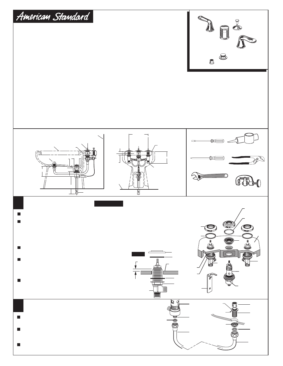
BIDET FAUCET INSTALLATION
Replace UPPER GASKET (8) and WASHER (7) and
ESCUTCHEON (6) until it locks against internal stop.
Position the side threaded outlet rearward and
secure MOUNTING NUT (11).
Remove ESCUTCHEON (6), WASHER (7) and
UPPER GASKET (8) from TRANSFER VALVE (9).
Insert TRANSFER VALVE (9) into the center forward
hole of BIDET.
COLD
HOT
BIDET
LEDGE
10
4
3a
3
8
9
1
5
2
6
SPRAY INSTALLATION
2
Assemble SPRAY BODY (1) to BIDET. Using putty, seal underside
of SPRAY BODY FLANGE (2) and secure with NUT (3).
Thread SPRAY CAP (9) onto SPRAY BODY (1).
Thread SPRAY HOSE (4) with SEAL WASHER (5) to SPRAY BODY (1).
Connect other end of HOSE (4) with SEAL WASHER (6) to side outlet
NIPPLE (7) of the TRANSFER VALVE (8).
PUTTY
6
2
7
8
1
9
Tighten LOCKNUTS (1) with WRENCH (5) (supplied)
to secure VALVE BODIES (3, 3a).
Install LOCKNUT (1) and RUBBER WASHER (2) onto VALVE BODIES (3, 3a). From
under side of mounting surface, install VALVE BODY (3, 3a) through valve mounting
holes. Threads of VALVE BODY (3, 3a) should extent at least 5/16 of a inch above
mounting surface top. Fig. A. Thread ESCUTCHEON (4) onto VALVE BODIES (3, 3a)
until snug against internal stop. If necessary, adjust LOCKNUT (1).
Place RUBBER RING (10) into ESCUTCHEON (4).
MOUNTING
SURFACE
4
10
2
1
3, 3a
5/16''
MIN.
Fig. A.
11
Adjustable Wrench
Screwdriver
Channel Locks
Required tools
Tubing Cutter
Phillips Screwdriver
Plumbers' Putty or
Caulking
7
1
Roughing-in
Dimensions
BIDET OUTLINE
IS SYMBOLIC
FINISHED
FLOOR
FINISHED
WALL
1-1/4 O.D. TAILPIECE
DOUCHE
SPRAY
2-1/8
DIA.
ADJ. 1-1/4
TO 2-1/4
3-7/8
5-1/2
1-3/8
DIA.
7/8 DIA.
1-1/4
MAX.
1-3/16
DIA.
2-1/4
DIA.
(C)
(H)
4-1/4
FOR GROUND JOINT
CONNECTION OR 1/2 "
O.D. SLIP (INLETS)
REAR VIEW WITH
WALL REMOVED
TRANSFER VALVE
(FOR FLUSHING
RIM OR SPRAY)
8 TO 12
Speed Connect Drain*
• Fewer parts, installs in less time
• Never needs adjustment
• Guaranteed to seal properly the first time, every time.