Installation, Tools required; fig. 2, Roughing-in dimensions – American Standard Selectronic 195 User Manual
Page 3: Install spout assembly; fig. 1, General description, Codes and standards
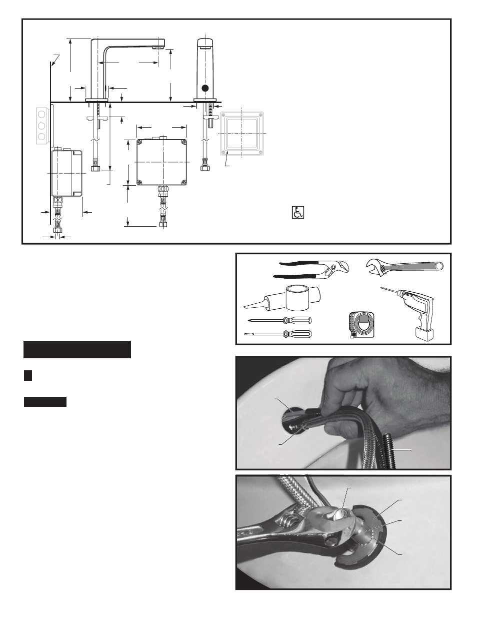
TOOLS REQUIRED; Fig. 2
Fig. 2
Fig. 1
1 Channel Locks
2 Adjustable Wrench
3 Plumbers' Putty or Caulking
4 Phillips Screwdriver
5 Flat Blade Screwdriver
6 Electric Drill & 1/4" Drill Bit
7 Tape Measure
1
2
3
4
5
6
7
Roughing-in Dimensions
10'
INSTALLATION
2
114mm
(4-1/2)
500mm
(20)
381mm
(15)
3/8" COMP.
32mm (1-1/4)
55.5mm
(2-3/16)
125mm
(4-7/8)
81mm
(3-3/16)
49mm
(2)
GENERAL DESCRIPTION:
Electronic faucet with proximity operation. Vandal
resistant solid brass construction single post
mounting. Operates on AC permanent power. Water
pressure range from 20 to 125 psi. In-line strainer
for solenoid is integral. Single inlet 3/8 compression,
built-in checks, and flexible stainless steel 15" reach
inlet hose for spout connection.
159mm
(6-1/4)
126mm
(5)
154mm
(6-1/16)
FINISHED
WALL
Fig. 1a
Fig. 1b
1
4
6
5
3
2
INSTALL SPOUT ASSEMBLY;
Fig. 1
CAUTION
Turn off hot and cold water
supplies before beginning
1
1. Insert WIRES (1), FLEX HOSE (2) and SPOUT
SHANK
(3) through center hole of mounting surface.
Fig. 1a.
2. Assemble "C" WASHER (4), STAR WASHER (5)
and LOCKNUT
(6) onto threads of SPOUT SHANK (7)
from underside of mounting surface.
Fig. 1b.
3. Align FAUCET and tighten LOCKNUT (6). Fig. 1b.
7
CODES AND STANDARDS:
These products meet or exceed the following
coded standards:
ANSI A117.1
ASME A112.18.1
CSA B 125
NSF 61/Section 9
ADA Compliant
M 9 6 5 2 74
ELECTRICAL BOX
OR EQUIVALENT
BY OTHERS
Note: All plumbing and electrical wiring must be
installed in accordance with applicable codes,
regulations and standards.