Vaddio ZoomSHOT WallVIEW Mini User Manual
Page 11
ZoomSHOT WallVIEW Mini
ZoomSHOT WallVIEW Mini System Document Number 342-0668 Rev A
Page 11 of 32
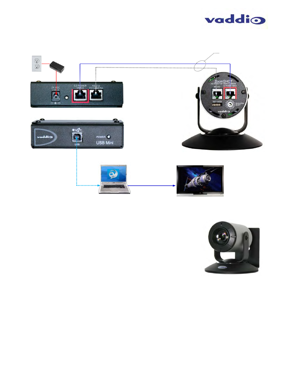
Diagram: Basic System Configuration ZoomSHOT with USB Mini
F
IRST
T
IME
S
ET
-
UP
:
The ZoomSHOT is very easy to use and operate. There is documentation at the
back of this manual for pin-outs of the connectors on the ZoomSHOT camera and
the USB Mini Interface.
Before Installing:
Choose the camera mounting location while paying close attention to camera
viewing angles, lighting conditions, possible line of site obstructions, and
checking for in-wall obstructions where the camera is to be mounted. Always
pick a mounting location that will optimize the performance of the camera.
Please locate the camera to enable easy positioning of the camera body with
the ability to point down and away from the ceiling and a bunch of fluorescent
lighting cells. Cameras generally do not like to be swamped with fluorescent
light and very few people sit on the ceiling anyway.
The Thin Profile Wall Mount (right) for the ZoomSHOT can be mounted directly to a 1-gang wall box or can be
mounted using only dry wall anchors.
For Power/Video and RS-232 signals, use standard Cat-5 cable (568B termination and real RJ-45
connectors) from the EZ-POWER VIDEO and RS-232 ports on the back of the ZoomSHOT to the Quick-
Connect SR Interface. The EZ-POWER VIDEO jack on the camera is highlighted
red
as a reminder that
there is 24 VDC power on that Cat-5 cable.
Local
Power
24 VDC
USB 2.0
Connected
to Front
Panel
Serial Control (RS-232)
◄
HD Video from Camera - Power to Camera
▶
Laptop with UC
Application
Room Monitor
(Simulated video feed)
HD Video
(HDMI, DVI
or RGBHV)
Quick-Connect USB Mini
Rear Panel (above), Front Panel (below)
Two (2) Cat-5 Cables
Distance up to 150’ (15.26m)
ZoomSHOT HD
Camera
USB 2.0
(UVC
Drivers)
Extension of PC Video
Image: ZoomSHOT HD
Camera with provided
Thin Profile Wall Mount