Universal motorpack parts list continued, Typical damper motor schematic, Universal motorpack parts list – COOK Universal Motor Pack User Manual
Page 2
2
14
1
2
3
13
12
11
4
5
6
7
8
10
6
6
7
8
9
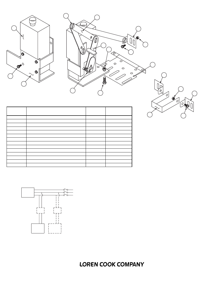
Item
No.
Description
Inventory
No.
Drawing
No.
1
Actuator Motor
554196
-
2
1/4” Long Screw Post & 8—32 Screw (4)
554225
-
3
Linkage Arm (4)
556764
-
4
Actuator Motor Arm
556766
-
5
1/4-20 Wizz Nut (4)
137555
-
6
Shutter Blade Bracket (3)
556128
556128-B
7
10-32 Nylock Nut (8)
137552
-
8
10—32 x 3/8” Wizz Bolt (8)
137573
-
9
Shutter Bracket
556121
556121-C
10
Two Panel Bracket
556123
556123-B
11
1/4—20 x 1/2” Wizz Bolt (4)
137578
-
12
Spring
554095
-
13
Actuator Motor Mounting Bracket
556126
556126-C
14
8—32 x 5/16” Hex Head Screw (4)
137502
-
Corporate Offices: 2015 E. Dale Street Springfield, MO 65803 417.869.6474
www.lorencook.com
Universal Motorpack Assembly Instructions - March 2005
* Lock-Tite all screw posts.
Universal Motorpack Parts List
Typical Damper Motor Schematic
For 3 phase, damper motor voltage should be the same between L
1
and
L
2
. For single phase application, disregard L
3
. *Damper motors may be
available in 115, 230 and 460 volt models. The damper motor nameplate
voltage should be verified prior to connection. ** A transformer may be
provided in some installations to correct the damper motor voltage to the
specified voltage.
Fan
Motor
Damper
Motor*
Second
Damper
Motor
Transformer**
Transformer**
L3
L2
L1