Maintenance, Inspection, Operation – COOK Power-Plume User Manual
Page 3: Wheel-to-inlet clearance, Wheel / inlet overlap 1/2” wiring installation, Use of variable frequency drives, Wheel rotation, Lubrication - motor bearings, Motor services, Motor replacement
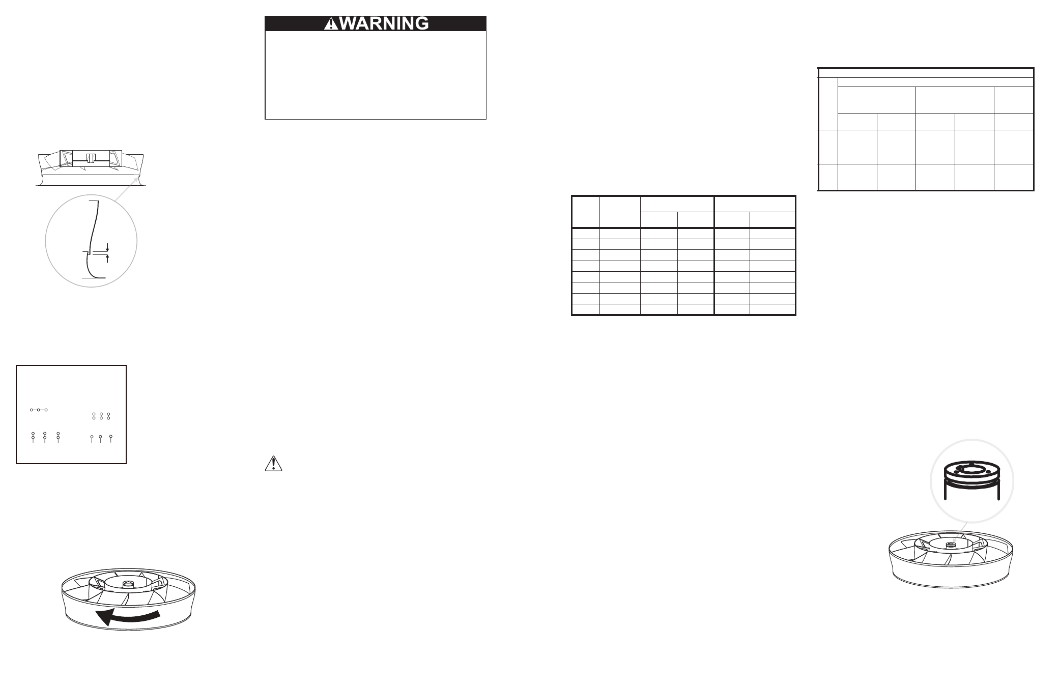
Wheel-to-Inlet Clearance
The correct wheel-to-inlet clearance is critical to proper
fan performance. This clearance should be verified before
initial start-up since rough handling during shipment could
cause a shift in fan components. Refer to wheel/inlet
drawing below for correct overlap.
Adjust the overlap by loosening the wheel hub and
moving the wheel along the shaft to obtain the correct
value. Trim balance as necessary (.0785 in/sec max).
A uniform radial gap (space between the edge of the
cone and the edge of the inlet) is obtained by loosening
the inlet cone bolts and repositioning the inlet cone.
Wheel / inlet
overlap 1/2”
Wiring Installation
All wiring should be in accordance with local ordinances
and the National Electrical Code, NFPA 70. Ensure the
power supply (voltage, frequency, and current carrying
capacity of wires) is in accordance with the motor
nameplate.
* Leads for L
1
L
2
L
3
are prewired to
disconnect switch
4 5 6
1
7
2
8
3
9
L1 L2 L3
4 5 6
7 8 9
1 2 3
L1 L2 L3
Low Voltage
208/230 Volts
High Voltage
460 Volts
3 Phase, 9 Lead Motor
Y-Connection
*
Use of Variable Frequency Drives
The low-speed (12-pole) motor used on the Power-
Plume is not suitable for use with a Variable Frequency
Drive (VFD). Use of a VFD will potentially damage the
motor and void the motor warranty.
Wheel Rotation
Test the fan to ensure the rotation of the wheel is the
same as indicated by the arrow marked Rotation.
prevent potentially catastrophic damage.
Tight clearances between the rotor and stationary
members could “freeze over” during non-operating hours.
Therefore, the unit should always be inspected to ensure
the rotor is released and air passageways are open and
clear of all debris prior to any restart.
NOTICE! Although a certain amount of vibration
is inherent in operating fans, extreme vibration is
a serious problem that may cause structural and
mechanical failure.
Inspection
Inspection of the fan should be conducted at the first
30 minute, 8 hour and 24 hour intervals of satisfactory
operation. During the inspections, stop the fan and inspect
bolts, setscrews, and motor mounting bolts. Adjust and
tighten as necessary.
Recommended Torque for Setscrews Bolts ( in / lbs. )
Size
Key Hex
Across
Flats
Recommended
Torque
Hold Down Bolts
Min.
Max.
Size
Wrench
Torque
No.10
3/32”
28
33
3/8”-16
240
1/4”
1/8”
66
80
1/2”-13
600
5/16”
5/32”
126
156
5/8”-11
1200
3/8”
3/16”
228
275
3/4”-10
2100
7/16”
7/32”
348
384
7/8”-9
2400
1/2”
1/4”
504
600
1” -8
3000
5/8”
5/16”
1104
1200
1 1/8”-7
4200
3/4”
3/8”
1440
1800
1 1/4”-7
6000
Maintenance
Establish a schedule for inspecting all parts of the fan.
The frequency of inspection depends on the operating
conditions and location of the fan.
Inspect fans exhausting corrosive or contaminated
air within the first month of operation. Fans exhausting
contaminated air (airborne abrasives) should be inspected
every three months.
Regular inspections are recommended for fans
exhausting non-contaminated air.
It is recommended the following inspection be
conducted twice per year.
• Inspect bolts and setscrews for tightness. Tighten as
necessary.
• Bearings should be inspected as recommended in the
Conditions Chart.
• Inspect for cleanliness. Clean exterior surfaces only.
Removing dust and grease on motor housing assures
proper motor cooling. Removing dirt from the wheel
and housing prevents imbalance and damage
Lubrication - Motor Bearings
Motors are provided with prelubricated bearings. Any
lubrication instructions shown on the motor nameplate
supersede instructions below.
Motor bearings without provisions for relubrication will
operate up to 10 years under normal conditions with no
maintenance. In severe applications, high temperatures
or excessive contaminates, it is advisable to have the
maintenance department disassemble and lubricate the
bearings after 3 years of operation to prevent interruption
of service.
For motors with provisions for relubrication, follow
intervals of the table below.
Motors are provided with a polyurea mineral oil NGLI #2
grease. All additions to the motor bearings are to be with a
compatable grease such as Exxon Mobil Polyrex EM and
Chevron SRI.
Relubrication Intervals
Service
Co
ndit
ion
s
NEMA Frame Size
Up to
and including
184T
213T-365T
404T
and larger
1800 RPM
and less
Over
1800 RPM
1800 RPM
and less
Over
1800 RPM
1800 RPM
and less
S
ta
n
d
a
rd
3 yrs.
6 months
2 yrs.
6 months
1 yr.
Severe
1 yr.
3 months
1 yr.
3 months
6 months
The above intervals should be reduced to half for
vertical shaft installations.
Motor Services
Should the motor prove defective within a one-year
period, contact your local Loren Cook representative
or your nearest authorized electric motor service
representative.
Motor Replacement
The motor can be removed using the following
sequence.
1. Disconnect the power to the Power-Plume®.
2. Disconnect the motor wires from the service switch
that is located on the motor housing.
3. Remove the top section of the fiberglass windband
4. Remove the cover plate from the wheel hub.
5. Loosen the set screws in the wheel and remove the
wheel from the motor shaft (see 3 steps below). The
wheel has a pre-machined shoulder on the hub for
the use of most 2 or 3 jaw mechanical pullers.
a Align center of the puller with center of the shaft.
b Ensure all setscrews in the hub, normally two,
are fully removed.
c Slowly remove the wheel from the shaft.
Pre-Machined
Shoulder
6. Remove the mounting bolts and motor lubrication
lines from the motor mounting plate.
7. Lift the motor using the supplied lifting lugs.
8. Remove the motor mounting bolts and motor
mounting plate.
To replace the motor reverse the steps used to remove.
Fire & Electrical Shock Hazard:
Do not allow the fan to run in the wrong direction. This
will overheat the motor and cause serious damage.
For 3-phase motors, if the fan is running in the wrong
direction, check the control switch. It is possible to
interchange two leads at this location so that the fan is
operating in the correct direction.
Final Installation Steps
1. Inspect fasteners and setscrews, particularly
fan mounting and bearing fasteners, and tighten
according to the recommended torque shown in the
table Recommended Torque for Setscrews/Bolts.
2. Inspect for correct voltage with voltmeter.
3. Ensure all accessories are installed.
Operation
Pre-Start Checks
1. Lock out all the primary and secondary power
sources.
2. Ensure fasteners and setscrews, particularly those
used for mounting the fan, are tightened.
3. Inspect motor wiring.
4. Ensure fan and ductwork are clean and free of
debris.
5. Inspect wheel-to-inlet clearance. The correct
wheel-to-inlet clearance is critical to proper fan
performance.
6. Close and secure all access doors.
7. Restore power to the fan.
Start Up
Turn the fan on. In variable speed units, set the fan to
its lowest speed and inspect for the following:
• Direction of rotation.
• Excessive vibration.
• Unusual noise.
• Bearing noise.
• Improper belt alignment or tension (listen for
squealing).
If a problem is discovered, immediately shut the fan
off. Lock out all electrical power and check for the
cause of the trouble. See Troubleshooting.
Winter Operation
When operating the Power-Plume in near or below
freezing weather there is always the potential for ice
buildup on any exposed surfaces, stationary or rotating.
Frequent inspection is very important for proper operation
of the unit. Under certain conditions severe ice buildup
can occur in a matter of minutes. These conditions are
not only produced by the weather but by the installation
as well. Only observation and experience will provide any
level of certainty for the safe and ice free operation of the
Power-Plume in any given location. If ice is discovered
during operation the unit should be shut down immediately
and the ice removed before operation is resumed.
A useful accessory for cold-climate operation is a
vibration cut-out switch. Should ice buildup begin, the
resulting vibration would be detected and the switch could
3
2