Inspection, Operation, Start up – COOK FCP User Manual
Page 4: Use of variable frequency drives, 30 minute interval, 8 hour interval, 24 hour interval, Pulley alignment, Final installation steps, Pre-start checks
4
9. Restore power to the fan.
Start Up
Turn the fan on. In variable speed units, set the fan to its
lowest speed and inspect for the following:
• Direction of rotation.
• Excessive vibration.
• Unusual noise.
• Bearing noise.
• Improper belt alignment or tension (listen for
squealing).
• Improper motor amperage or voltage.
NOTICE! If a problem is discovered, immediately
shut the fan off. Lock out all electrical power and check
for the cause of the trouble. See Troubleshooting.
Use of Variable Frequency Drives
Motors:
Motors that are to be operated using a Variable Frequency
Drive (VFD) must be VFD compatible. At a minimum, this
must be a Premium Efficiency motor with Class F
insulation. Motors that are not supplied by Loren Cook
Company should have the recommendation of the motor
manufacturer for use with a VFD.
Grounding:
The fan frame, motor and VFD must be connected to a
common earth ground to prevent transient voltages from
damaging rotating elements.
Wiring:
Line reactors may be required to reduce over-voltage
spikes in the motors. The motor manufacturer should be
consulted for recommended line impedence and usage of
line reactors or filters, if the lead length between the VFD
and the motor exceeds 10 feet (3m).
Fan:
It is the responsibility of the installing body to perform
coast-down tests and identify any resonant frequencies
after the equipment is fully installed. These resonant
frequencies are to be removed from the operating range of
the fan by using the “skip frequency” function in the VFD
programming. Failure to remove resonant frequencies from
the operating range will decrease the operating life of the
fan and void the warranty.
Inspection
Inspection of the fan should be conducted at the first 30
minute, 8 hour and 24 hour intervals of satisfactory
operation. During the inspections, stop the fan and inspect
as per the Conditions Chart.
30 Minute Interval
Inspect bolts, setscrews, and motor mounting bolts.
Adjust and tighten as necessary.
8 Hour Interval
Inspect belt alignment and tension. Adjust and tighten as
necessary.
24 Hour Interval
Inspect belt tension, bolts, setscrews, and motor
mounting bolts. Adjust and tighten as necessary.
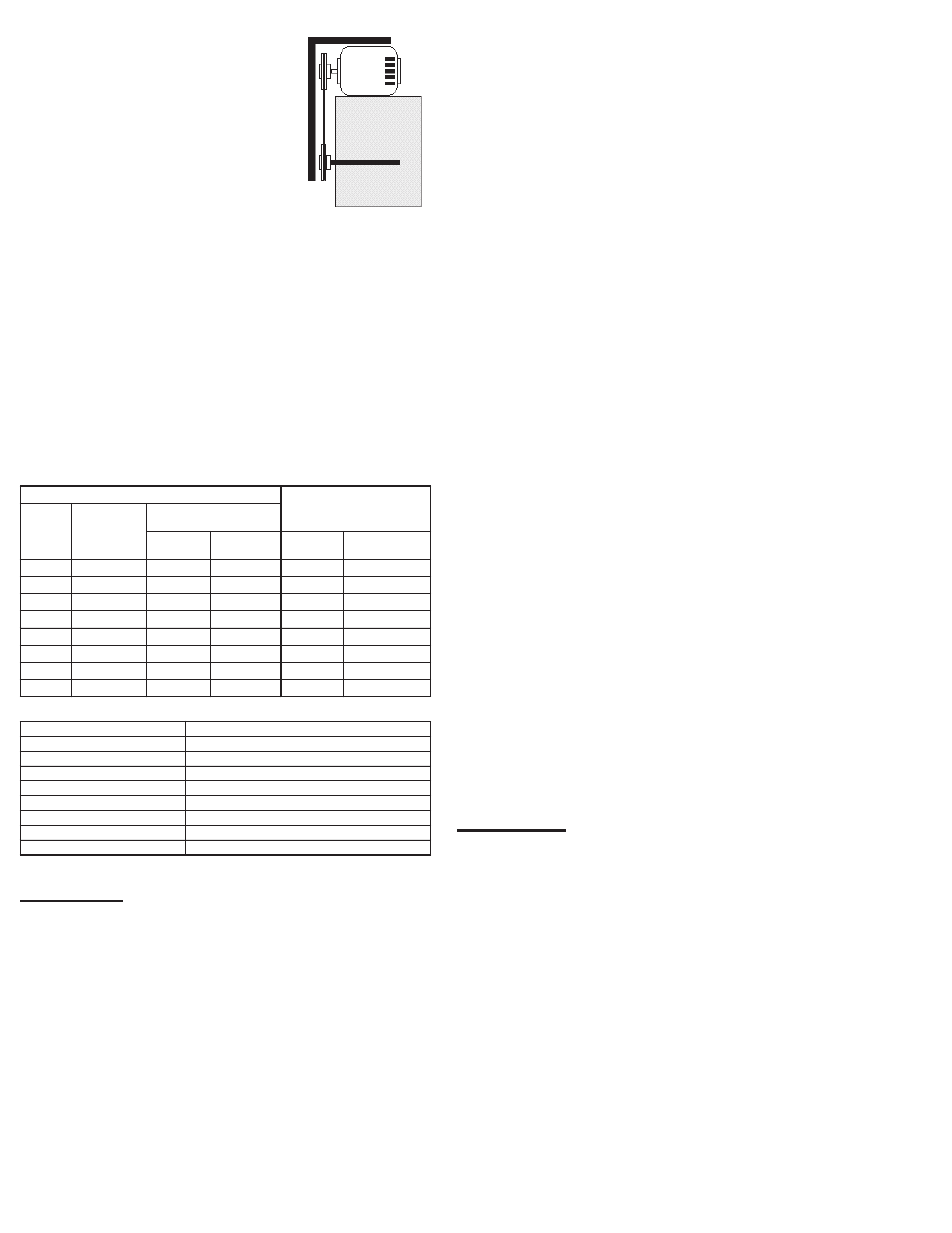
Pulley Alignment
Pulley alignment is adjusted by
loosening the motor pulley setscrew and
by moving the motor pulley on the motor
shaft.
Figure 4 indicates where to measure
the allowable gap for the drive alignment
tolerance. All contact points (indicated
by WXYZ) are to have a gap less than
the tolerance shown in the table. When
the pulleys are not the same width, the
allowable gap must be adjusted by half of the difference in
width (As shown in A & B of Figure 4). Figure 5 illustrates
using a carpenter’s square to adjust the position of the
motor pulley until the belt is parallel to the longer leg of the
square.
Final Installation Steps
1. Inspect fasteners and setscrews, particularly fan
mounting and bearing fasteners, and tighten according
to the recommended torque shown in the following
table.
2. Inspect for correct voltage with voltmeter.
3. Ensure all accessories are installed.
Recommended Torque for Setscrews/Bolts on metal (IN-LB)
Recommended Torque for Setscrews/Bolts on FRP (FT-LB)
Operation
Pre-Start Checks
1. Lock out all the primary and secondary power sources.
2. Ensure fasteners and setscrews, particularly those
used for mounting the fan, are tightened.
3. Inspect belt tension and pulley alignment.
4. Inspect motor wiring.
5. Ensure belt touches only the pulleys.
6. Ensure fan and ductwork are clean and free of debris.
7. Inspect wheel-to-inlet clearance. The correct wheel-to-
inlet clearance is critical to proper fan performance.
8. Close and secure all access doors.
Setscrews
Hold Down Bolts
Size
Key Hex
Across
Flats
Recommended
Torque
Min.
Max.
Size
Wrench
Torque
No.10
3/32”
28
33
3/8”-16
240
1/4”
1/8”
66
80
1/2”-13
600
5/16”
5/32”
126
156
5/8”-11
1200
3/8”
3/16”
228
275
3/4”-10
2100
7/16”
7/32”
29
348
7/8”-9
2040
1/2”
1/4”
42
504
5/8”
5/16”
92
1104
3/4”
3/8”
120
1440
Size
18-8 SST Hardware Torque
No 10
7
1/4”
12
5/16”
20
3/8”
30
7/16”
41
1/2”
54
5/8”
86
3/4”
128
Figure 5