Operation, Maintenance – COOK ERV Evaporator Coil Supplement User Manual
Page 2
2
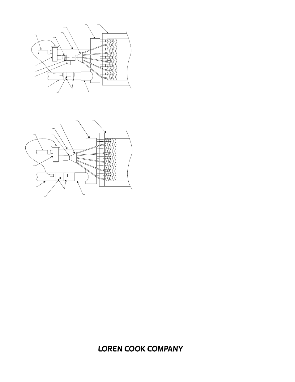
Suction Line
Expansion Valve
Remote Sensing Bulb
Straps
Suction Connection
Coil
Suction Header
Distributor
Equalizer Line
Nozzle
Liquid Line
12.
Refer to Figure 4 - Hot Gas Bypass Kit Installed and Fig-
ure 5 - General Diagram, for general piping.
Operation
1.
Proper air distribution is vital to coil performance. Air flow
anywhere on the coil face should not vary by more than 20%.
2.
Air velocities should be maintained between 200 and 550
feet per minute.
3.
The drain pan should be designed and installed such that
there is no standing water.
Maintenance
1.
Filters should be inspected on a regular basis and changed
as needed. Maintaining clean filters is a cost-effective way to help
maintain maximum coil performance and service life.
2.
Periodic inspection of the coil for signs of corrosion and for
leaks is recommended. Small leaks can be detected using a
Halide torch. Repair and replacement of the coil and the connect-
ing piping, valves, etc., should be performed as needed by a qual-
ified individual(s).
3.
Should the coil surface need cleaning, caution should be
exercised in selecting the cleaning solution as well as the cleaning
equipment. Improper selection can result in damage to the coil
and/or health hazards. Clean the coil from the leaving air-side so
that foreign material will be washed out of the coil rather than
pushed further in. Be sure to carefully read and follow the manu-
facturer’s recommendations before using any cleaning fluid.
4.
The use of filter-dryers in the system piping is recommended
along with a sight glass that has a moisture indicator. Replace the
filter dryer(s) as needed.
Note:
Refrigerant conversions are beyond the scope of this
manual and should only be performed by qualified parties.
Corporate Offices:
2015 E. Dale Street
Springfield, MO 65803 417.869.6474
lorencook.com
ERV Evaporator Coil IOM Supplement- December 2002
Remote Sensing Bulb
Suction Line
Liquid Line
Nozzle
Equalizer Line
Distributor
Suction Header
Coil
Expansion Valve
Hot Gas By-Pass
Hot Gas Side Port
Straps
Suction Connection
Figure 4 - Hot Gass Bypass Kit Installed
Figure 5 - General Diagram