Operation, Real time pressure, Motor output percentage – COOK Constant Pressure Control System User Manual
Page 2: Set point, Status, Hour meter, Electrical interferences hazard, Wiring diagram
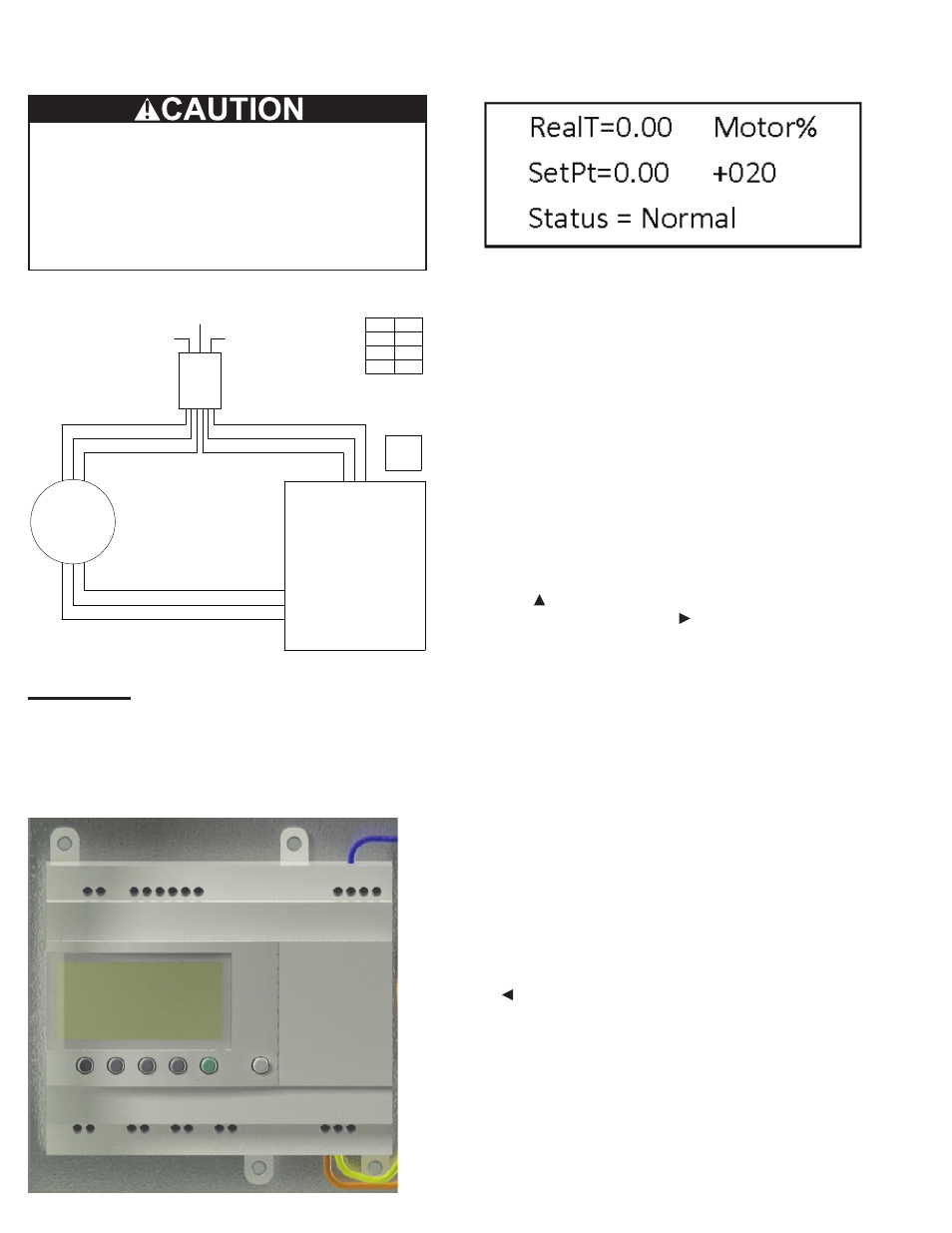
The controller comes pre-programmed from the
factory. At initial power-up, the controller initiates and
the target pressure will be set at 0.00” w.g. and the
display will show the main screen as shown below.
Real Time Pressure
The actual real time pressure reading is displayed in
the field labeled RealT and is given in inches of water
gage.
Motor Output Percentage
The current motor output percentage is displayed
under the field labeled Motor%. This is the measure of
the motor speed that is currently being called for by the
controller. The value varies from 20 to 100 percent. The
motor will shut down when the value called for drops
below 20 percent.
Set Point
The current set point value is displayed in the field
labeled SetPt and is given in inches of water gage.
The set point can be changed using the third and fourth
buttons from the left edge of the controller. The button
with the symbol below it will increase the set point
value and the button with the symbol will decrease the
set point value.
Status
The display will also give the user feedback as to what
state the controller is operating.
• Normal:
If the pressure is within the acceptable range of the
set point and the motor speed is stabilized, the status
will be given as Normal.
• Max:
If the controller is calling for more fan output but the
motor is at the maximum rpm, the status will be given
as Max.
• Min:
If the controller is calling for less fan output but the
motor is at the minimum rpm, the status will be given
as Min.
Hour Meter
During normal operating mode, push the button with
the below it and the display will give a read out of the
number of hours that controller has been operating.
Connect the low voltage input wires from the EC motor
to the output connections for the control box per the
wiring diagram.
Electrical Interferences Hazard:
Low-voltage control wires and high-voltage power
wires must be installed in separate conduit from
control box to the EC motor.
Failure to follow these instructions could result in
malfunction or damage.
Wiring Diagram
SPECIAL DRAWING TITLE BLOCK INFO COMES FROM DRAWING i-Properties
SUMMARY/COMMENTS
Pressure Control Box
EC Motor
DS
by
Others
A
B
C
1 2 3
Control Signal - Red (0-10 VDC)
Common - White
Logic Control Power - Black (24 VAC)
Black (115 VAC - Hot)
White (115 VAC - Neutral)
Green (Ground)
Green (Ground)
White (115 VAC - Neutral)
Black (115 VAC - Hot)
Ground
115 VAC - Neutral
115 VAC - Hot
Hp FLA
1/4
3.8
1/2
6.3
3/4
9.5
1 AMP
Max
Operation
The controller is shown below. It has a LCD screen
that gives feedback as to the actual pressure reading,
pressure set point, motor operating percent, and status.
It also has six buttons that change the set point as well as
give access to other controller functions.
Figure 4 Note: Allow for ceiling thickness.
Suggested Installation: Unit with filter.
Constant Pressure Control System
For electronically commutated motors IOM - April 2012