Loren cook company – COOK Automatic Belt Tensioner Supplement II User Manual
Page 2
2
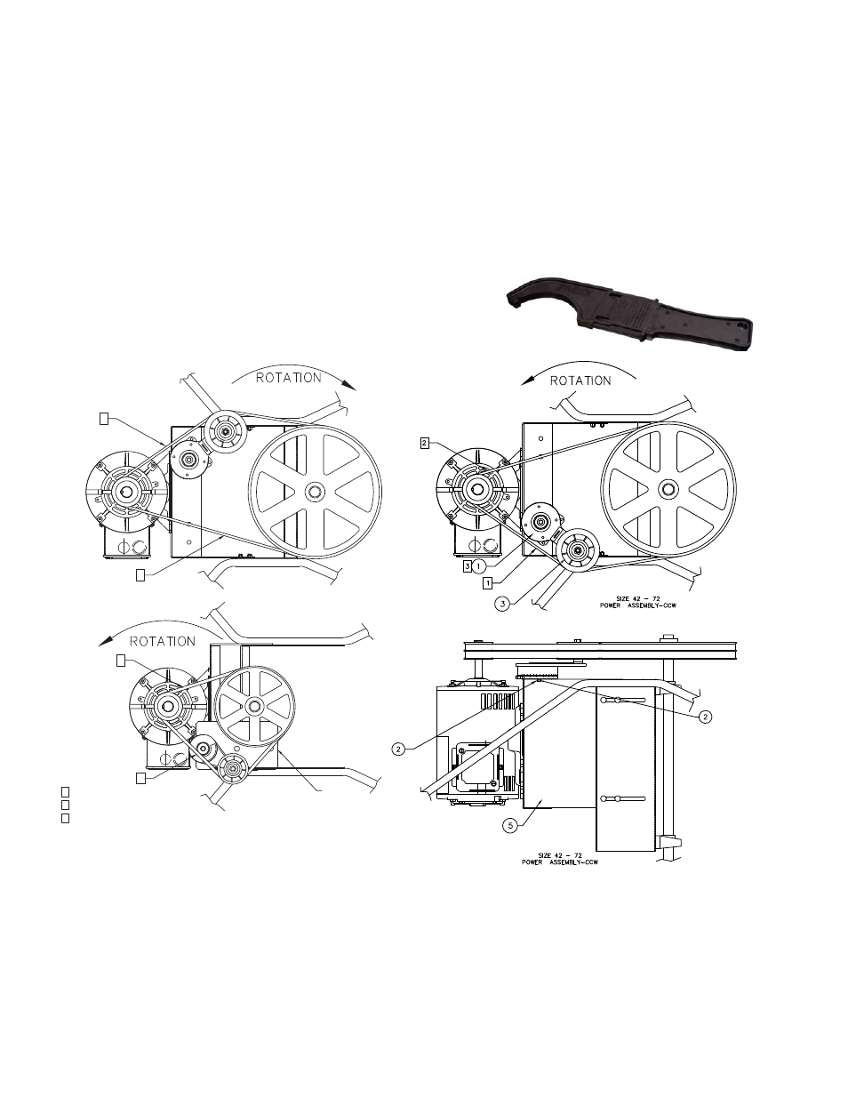
Size 42 - 72
Power Assembly-CW
1
2
2
1
Size 20 - 36
Power Assembly
MOUNTING
BRACKET
1
2
3
SLACK SIDE OF BELT
NOTES:
TENSION SIDE OF BELT
IF NECESSARY, ADJUST HEIGHT
OF TENSIONER WITH SHIMS
Limited Warranty
Loren Cook Company warrants that your Loren Cook fan was manufactured free of defects in materials and workmanship, to the extent stated herein. For a period of one (1)
year after date of shipment, we will replace any parts found to be defective without charge, except for shipping costs which will be paid by you. This warranty is granted only to
the original purchaser placing the fan in service. This warranty is void if the fan or any part thereof has been altered or modified from its original design or has been abused, mis-
used, damaged or is in worn condition or if the fan has been used other than for the uses described in the company manual. This warranty does not cover defects resulting from
normal wear and tear. To make a warranty claim, notify Loren Cook Company, General Offices, 2015 East Dale Street, Springfield, Missouri 65803-4637, explaining in writing,
in detail, your complaint and referring to the specific model and serial numbers of your fan. Upon receipt by Loren Cook Company of your written complaint, you will be notified,
within thirty (30) days of our receipt of your complaint, in writing, as to the manner in which your claim will be handled. If you are entitled to warranty relief, a warranty adjustment
will be completed within sixty (60) business days of the receipt of your written complaint by Loren Cook Company. This warranty gives only the original purchaser placing the fan
in service specifically the right. You may have other legal rights which vary from state to state.
Corporate Offices: 2015 E. Dale Street Springfield, MO 65803 417.869.6474
lorencook.com
LOREN COOK COMPANY
Automatic Belt Tensioner Supplement II - March 2010
the tensioner cannot be reassembled.
The RT4000 tensioner requires considerable force to
overcome it’s spring tension. If force is so strong that
the procedure given in Note 6 won’t work, use the fol-
lowing procedure. With tensioner mounting bolt only
finger tight, rotate tensioner back so that belts can be
installed easily. Now rotate tensioner arm until belts
begin to tighten and you feel light spring tension. Hook
in provided spanner wrench and rotate tensioner arm
until alignment marks are 3/4 apart. While holding
spanner wrench securely at this position, tighten ten-
sioner mounting bolt fully and remove spanner wrench.
3.Once installed, the RT4000 tensioner has considerable
force.
sioner counterclockwise an additional 1/2”, and repeat
steps 6 and 7.
RT3000/RT4000 Installation Notes:
1.The tensioner comes with a limited-use spanner
wrench. The spanner wrench must be used to hold the
tensioner base when loosening the mounting bolt.
2. The RT3000 and RT4000 have a directional arrow to
ensure proper installation. The arrow must always point
toward the belt being tensioned. In this application,
units with counterclockwise rotation point clockwise and
clockwise rotation point counter clockwise. If arrow is
pointing the wrong direction, remove the back of ten-
sioner housing and the spring. Then flip the spring over,
the spring’s center “tail” must engage the slot in the
center shaft. Then push out the directional arrow piece
located in the arm assembly, and reverse the arrow so
it points the opposite way and snap in place. Note that if
the arrow piece is not pointing in the correct direction,